Cable Descriptions Chapter 3: Cable Descriptions Cable Descriptions ■ ■ ■ ■ ■ ■ ■ ■ ■ ■ ■ ■ ■ ■ ■ ■ ■ ■ ■ ■ ■ ■ ■ ■ ■ ■ ■ ■ ■ ■ ■ ■ ■ ■ ■ ■ ■ ■ ■ ■ ■ ■ ■ ■ ■ ■ ■ ■ ■ ■ ■ ■ ■ ■ ■ ■ ■ ■ ■ ■ ■ ■ ■ ■ Overview This chapter provides the descriptions of the site cabling. Procedures for routing cables (through metallic or conductive conduit) to the outdoor equipment are found in Chapter 4 Access Point Hardware Installation .
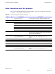
Access Point Hardware Installation Cable Descriptions Cable Descriptions and Part Numbers Table 3-1 gives the cable descriptions and part numbers of the various cables that will connect to the Base Control Unit (BCU) and RF head. Table 3-1 Cable Description and Part Numbers Cable Qty A 2 B 2–8 C 1 Part Number Description Customer Supplied Ground cable, 6 AWG or larger, insulated copper wire. Requires one two-hole lug connectors. 3089492T02 Antenna Cable, 300 mm (1 ft.
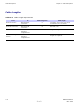
Cable Descriptions Chapter 3: Cable Descriptions Cable Lengths Table 3-2 Cable Length Requirements From To Cable Designation Cable length BCU DC Source RF Head DC Connector G 5 lengths, 20 to 100 m in 20 m increments (65.6 to 328 ft) BCU RF Connector RF Head RF Connector B 300 mm (1 ft) AC Source BCU Customer Interface Compartment E Length as required. Customer Output Source BCU Customer Interface Compartment F Length as required.
Access Point Hardware Installation Earth Ground and Power Cables Earth Ground and Power Cables ■ ■ ■ ■ ■ ■ ■ ■ ■ ■ ■ ■ ■ ■ ■ ■ ■ ■ ■ ■ ■ ■ ■ ■ ■ ■ ■ ■ ■ ■ ■ ■ ■ ■ ■ ■ ■ ■ ■ ■ ■ ■ ■ ■ ■ ■ ■ ■ ■ ■ ■ ■ ■ ■ ■ ■ ■ ■ ■ ■ ■ ■ ■ ■ The objective of this procedure is to install the power and earth ground cabling for the Base Control Unit (BCU) and RF Head.
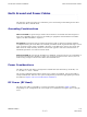
Earth Ground and Power Cables Chapter 3: Cable Descriptions Table 3-3 RF Head DC Power Cable Description and Part Numbers Part Number Description Cable Qty F 1–4 3089298C01 Power Cable, 20 m (65.6 ft) 1–4 3089298C02 Power Cable, 40 m (131.2 ft) 1–4 3089298C03 Power Cable, 60 m (196.8 ft) 1–4 3089298C04 Power Cable, 80 m (262.4 ft) 1–4 3089298C05 Power Cable, 100 m (328.
Access Point Hardware Installation Antenna Cable Antenna Cable ■ ■ ■ ■ ■ ■ ■ ■ ■ ■ ■ ■ ■ ■ ■ ■ ■ ■ ■ ■ ■ ■ ■ ■ ■ ■ ■ ■ ■ ■ ■ ■ ■ ■ ■ ■ ■ ■ ■ ■ ■ ■ ■ ■ ■ ■ ■ ■ ■ ■ ■ ■ ■ ■ ■ ■ ■ ■ ■ ■ ■ ■ ■ ■ Objective This section contains general information on the antenna cabling. Cable Label Refer to Table 3-1 for the labels used to identify the cables that will be shown in illustrations throughout this chapter.
Remote GPS Cable Chapter 3: Cable Descriptions Remote GPS Cable ■ ■ ■ ■ ■ ■ ■ ■ ■ ■ ■ ■ ■ ■ ■ ■ ■ ■ ■ ■ ■ ■ ■ ■ ■ ■ ■ ■ ■ ■ ■ ■ ■ ■ ■ ■ ■ ■ ■ ■ ■ ■ ■ ■ ■ ■ ■ ■ ■ ■ ■ ■ ■ ■ ■ ■ ■ ■ ■ ■ ■ ■ ■ ■ Objective This section contains general information on the Remote Global Positioning System (RGPS) cabling. Installation information is found in Chapter 4 Access Point Hardware Installation, beginning with Procedure 4-6 .
Access Point Hardware Installation Remote GPS Cable • The mounting pipe for the RGPS head should be mounted vertically with less than five degrees of tilt. • It is recommended that the RGPS head be installed using the supplied mounting mast and mounting hardware. Care should be taken to ensure that the RGPS chassis does not come into contact with any metal surfaces. Failure to properly isolate the RGPS chassis from other conductive surfaces can lead to RGPS head failure.
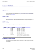
RF GPS Cable Chapter 3: Cable Descriptions RF GPS Cable ■ ■ ■ ■ ■ ■ ■ ■ ■ ■ ■ ■ ■ ■ ■ ■ ■ ■ ■ ■ ■ ■ ■ ■ ■ ■ ■ ■ ■ ■ ■ ■ ■ ■ ■ ■ ■ ■ ■ ■ ■ ■ ■ ■ ■ ■ ■ ■ ■ ■ ■ ■ ■ ■ ■ ■ ■ ■ ■ ■ ■ ■ ■ ■ Objective This section contains general information on the Radio Frequency Global Positioning System receiver (RF GPS) antenna cabling. More commonly referred to as Local GPS. Refer to for installation information.
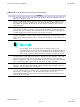
Access Point Hardware Installation Table 3-8 RF GPS Cable Local GPS Antenna Mounting Considerations Heading2 1 The mounting pipe for the Local GPS Head should be mounted vertically with less than five (5) degrees of tilt. 2 The Local GPS Head requires a clear view of the sky, preferably to within ten (10) degrees of the horizon in all directions. The more sky that is observed increases the number of potential satellites that can be tracked, resulting in better Local GPS performance.
Ethernet Cable Chapter 3: Cable Descriptions Ethernet Cable ■ ■ ■ ■ ■ ■ ■ ■ ■ ■ ■ ■ ■ ■ ■ ■ ■ ■ ■ ■ ■ ■ ■ ■ ■ ■ ■ ■ ■ ■ ■ ■ ■ ■ ■ ■ ■ ■ ■ ■ ■ ■ ■ ■ ■ ■ ■ ■ ■ ■ ■ ■ ■ ■ ■ ■ ■ ■ ■ ■ ■ ■ ■ ■ Objective This section contains general information on the Ethernet Cabling. Refer to Chapter 4 Access Point Hardware Installation for ethernet cable installation information.
Access Point Hardware Installation Fiber Optic Cable Fiber Optic Cable ■ ■ ■ ■ ■ ■ ■ ■ ■ ■ ■ ■ ■ ■ ■ ■ ■ ■ ■ ■ ■ ■ ■ ■ ■ ■ ■ ■ ■ ■ ■ ■ ■ ■ ■ ■ ■ ■ ■ ■ ■ ■ ■ ■ ■ ■ ■ ■ ■ ■ ■ ■ ■ ■ ■ ■ ■ ■ ■ ■ ■ ■ ■ ■ Objective This section contains general information on the fiber optic cable Cable Label Refer to Table 3-1 for the labels used to identify the cables that will be shown in illustrations throughout this chapter.
Customer Dened Input/Output Cables Chapter 3: Cable Descriptions Customer Dened Input/Output Cables ■ ■ ■ ■ ■ ■ ■ ■ ■ ■ ■ ■ ■ ■ ■ ■ ■ ■ ■ ■ ■ ■ ■ ■ ■ ■ ■ ■ ■ ■ ■ ■ ■ ■ ■ ■ ■ ■ ■ ■ ■ ■ ■ ■ ■ ■ ■ ■ ■ ■ ■ ■ ■ ■ ■ ■ ■ ■ ■ ■ ■ ■ ■ ■ Objective This section contains general information on the Customer Defined Input (CDI) and Output (CDO) cables. Refer to Chapter 4 Access Point Hardware Installation for installation information.
Access Point Hardware Installation Customer Dened Input/Output Cables Customer Dened Input and Output Connector Pinouts Input Pins Table 3-11 lists the pinouts for the Customer Defined Input 1-4 and 5–8 connectors. Refer to Figure 4-17.
Customer Dened Input/Output Cables Chapter 3: Cable Descriptions Output Pins Table 3-13 lists the pinouts for the Customer Defined Output connectors 1-2 and 3-4.
Chapter 4 Access Point Hardware Installation ■ ■ ■ ■ ■ ■ ■ ■ ■ ■ ■ ■ ■ ■ ■ ■ ■ ■ ■ ■ ■ ■ ■ ■ ■ ■ ■ ■ ■ ■ ■ ■ ■ ■ ■ ■ ■ ■ ■ ■ ■ ■ ■ ■ ■ ■ ■ ■ ■ ■ ■ ■ ■ ■ ■ ■ ■ ■ ■ ■ ■ ■ ■ ■ ■ ■ 68P09277A59-5 OCT 2006 4-1 Draft
Installation Overview Chapter 4: Access Point Hardware Installation Installation Overview ■ ■ ■ ■ ■ ■ ■ ■ ■ ■ ■ ■ ■ ■ ■ ■ ■ ■ ■ ■ ■ ■ ■ ■ ■ ■ ■ ■ ■ ■ ■ ■ ■ ■ ■ ■ ■ ■ ■ ■ ■ ■ ■ ■ ■ ■ ■ ■ ■ ■ ■ ■ ■ ■ ■ ■ ■ ■ ■ ■ ■ ■ ■ ■ Overview This chapter provides procedures for Base Control Unit (BCU) and RF Head installation and associated cabling. All required cables have been installed at the site and routed to the BCU.
Access Point Hardware Installation Installation Overview 1. Attach the BCU mounting bracket assembly to wall/pole or mount on pedestal 2. Install BCU. 3. Attach the RF Head mounting bracket assembly to pole 4. Install RF Head 5. Install Antennas 6. Install RGPS or RF GPS antenna 7. Connect earth ground cables To BCU To RF Head Between RF Head and tower Between antennas and tower To GPS 8. Connect AC power cable 9. Connect DC power cables from RF Head to BCU 10.
Installation Overview Chapter 4: Access Point Hardware Installation GPS Kits The following items are the Global Positioning System (GPS) kits that may have been shipped to the site.
Access Point Hardware Installation Connector Locations Connector Locations ■ ■ ■ ■ ■ ■ ■ ■ ■ ■ ■ ■ ■ ■ ■ ■ ■ ■ ■ ■ ■ ■ ■ ■ ■ ■ ■ ■ ■ ■ ■ ■ ■ ■ ■ ■ ■ ■ ■ ■ ■ ■ ■ ■ ■ ■ ■ ■ ■ ■ ■ ■ ■ ■ ■ ■ ■ ■ ■ ■ ■ ■ ■ ■ Base Control Unit Connector Locations Figure 4-1 shows the location of the cable connectors on the BCU. RF Head Connector Locations Refer to Figure 1-4 for the location of the cable connectors on the RF Head.
Base Control Unit Installation Chapter 4: Access Point Hardware Installation Base Control Unit Installation ■ ■ ■ ■ ■ ■ ■ ■ ■ ■ ■ ■ ■ ■ ■ ■ ■ ■ ■ ■ ■ ■ ■ ■ ■ ■ ■ ■ ■ ■ ■ ■ ■ ■ ■ ■ ■ ■ ■ ■ ■ ■ ■ ■ ■ ■ ■ ■ ■ ■ ■ ■ ■ ■ ■ ■ ■ ■ ■ ■ ■ ■ ■ ■ Overview This section contains procedures for installing a Base Control Unit (BCU). Refer to Figure 1-1 for an overall view of the BCU.
Access Point Hardware Installation Figure 4-1 Base Control Unit Installation BCU Card Cage Compartment Fan PSU 2 PSU 1 PSU 3 Circuit Breakers Alarm Card Modem Cards Controller Cards Heaters 68P09277A59-5 ti-cdma-04167.
Base Control Unit Installation Chapter 4: Access Point Hardware Installation Figure 4-2 BCU Power and Customer Interface Compartment RF -GPS Module Customer Input / Output connectors AC Power compartment with cover removed RGPS connector behind cover Ethernet connections ti-cdma-04174.eps Electrical The BCU is designed to use 100–240 VAC, +27 VDC, or —48 VDC. If powered by single phase AC voltage (customer supplied), the range is 100–240 V (88–300 VRMS) at 45–66 Hz.
Access Point Hardware Installation Base Control Unit Installation Battery Backup Battery backup or associated charging/control circuitry for the AC version of the BCU is not supported. Dimension and Weight If the BCU must be physically adjusted/moved, Motorola recommends that a minimum of two people perform this function. • Dimension: 508 mm (20 in.) W x 760 mm (30 in.) H x 508 mm (20 in.) D • Weight: 68 kg (150 lbs) The dimension measurements do not include connectors, hinges, handles, or latches.
Base Control Unit Installation Chapter 4: Access Point Hardware Installation • Bucklestrap Cutting Tool (Motorola P/N 6604809N01) for pole mounting bracket assembly • Safety Glasses • 13/16 Breakaway Torque Wrench 38 in-lb • Chalk • Tape Measure • Electrical Tape • Crescent Wrench • Socket Driver • Metric or Standard Socket Set for 1/4–in or 3/8–in driver BCU Mounting Bracket Assembly Installation Figure 4-3 shows the Wall Mounting Bracket and Mounting Bracket Assembly.
Access Point Hardware Installation Base Control Unit Installation BCU Mounting Bracket Assembly Procedure Pole Mount Follow the procedure in Procedure 4-1 to install the pole mounting bracket assembly and wall mounting bracket for pole mounting the BCU. Once the BCU is installed, DO NOT use it as a step ladder. It is not designed to support a person hanging from or standing on top of it.
Base Control Unit Installation Procedure 4-1 Chapter 4: Access Point Hardware Installation Procedure to Install Mounting Bracket Assembly on a Pole (Continued) 7 Use the hammer to bend buckle tabs over strap. Use electrical tape to cover over the buckle and straps. 8 Perform step 3 through step 8, for the remaining straps. 9 Secure Mounting Bracket to Pole Mounting Bracket Assembly using 9 M6 bolts and washers (Refer to Figure 4-3). Torque bolts to 3.4 N–m (30 in–lbs).
Access Point Hardware Installation Base Control Unit Installation Procedure 4-2 Procedure to Install the BCU (Continued) 9 For Customer Input and Output cable installation, perform Procedure 4-10. To avoid confusion tag the output cables. 10 For ethernet cable installation (if available), perform Procedure 4-8 .
Diversity Access Point (DAP) RF Head Assembly Installation Chapter 4: Access Point Hardware Installation Diversity Access Point (DAP) RF Head Assembly Installation ■ ■ ■ ■ ■ ■ ■ ■ ■ ■ ■ ■ ■ ■ ■ ■ ■ ■ ■ ■ ■ ■ ■ ■ ■ ■ ■ ■ ■ ■ ■ ■ ■ ■ ■ ■ ■ ■ ■ ■ ■ ■ ■ ■ ■ ■ ■ ■ ■ ■ ■ ■ ■ ■ ■ ■ ■ ■ ■ ■ ■ ■ ■ ■ Overview This section contains the procedures for installing the Diversity Access Point RF Head Assembly which is comprised of the RF Head and antenna rad
Access Point Hardware Installation Diversity Access Point (DAP) RF Head Assembly Installation Tools and Materials • Mounting Bracket Assembly • U-bolts • Set of metric sockets (3/8–in or 1/4–in drivers) • Set of standard sockets (3/8–in or 1/4–in drivers) • Socket 3/8–in or 1/4–in driver • Torque Driver • Cordless Power Driver • Ground Lug • Crimp Tool • T30 Torx Screw Driver • Adjustable Crescent Wrench • Tie-wraps of varying lengths U-Bolt Specications Reference Figure A-1 and T
Diversity Access Point (DAP) RF Head Assembly Installation Chapter 4: Access Point Hardware Installation Figure 4-4 U-Bolt Sizing C B ti-cdma-05727.eps Table 4-3 DAP U-Bolt Sizing Minimum Dimension B Pipe OD Minimum Dimension C (in) (mm) (in) (mm) (in) (mm) 2.067 52.50 3.886 98.70 0.6 15 2.469 62.71 4.429 112.50 0.6 15 3.068 77.93 5.098 129.50 0.
Access Point Hardware Installation Figure 4-5 Diversity Access Point (DAP) RF Head Assembly Installation RF Head Assembly ti-cdma-05725.eps Procedure 4-3 Procedure to Install RF Head Assembly 1 If cables have already been routed to the tower, proceed to step 4.
Diversity Access Point (DAP) RF Head Assembly Installation Procedure 4-3 Chapter 4: Access Point Hardware Installation Procedure to Install RF Head Assembly (Continued) 2 On the inside of the Customer Interface Compartment are color coded stickers and matching tie-wraps. The colors are matched to the RF Head DC power cables. The colors are as follows: • RFU 1 = RED • RFU 2 = BLUE • RFU 3 = YELLOW • RFU 4 = GREEN Remove the appropriate color sticker and apply it to the underside of the RF Head.
Access Point Hardware Installation Procedure 4-3 Diversity Access Point (DAP) RF Head Assembly Installation Procedure to Install RF Head Assembly (Continued) 10 Ensure that the RF Head is properly mounted and its movement is not obstructed. To adjust the azimuth (up/down angle) loosen 2 M6 screws on each side of unit using a 10 mm socket or crescent wrench. Range of motion is 25 degrees from horizontal. The retention bracket serves as an indicator of the azimuth in degrees.
Ground Cabling Installation Chapter 4: Access Point Hardware Installation Ground Cabling Installation ■ ■ ■ ■ ■ ■ ■ ■ ■ ■ ■ ■ ■ ■ ■ ■ ■ ■ ■ ■ ■ ■ ■ ■ ■ ■ ■ ■ ■ ■ ■ ■ ■ ■ ■ ■ ■ ■ ■ ■ ■ ■ ■ ■ ■ ■ ■ ■ ■ ■ ■ ■ ■ ■ ■ ■ ■ ■ ■ ■ ■ ■ ■ ■ Objective This section contains the procedures for installing the ground cable to the Antenna, BCU, RGPS, and RF Head.