
Installation Manual


Installing Wall Mount Fixed Wireless Terminal
4/98
2-13
Fixed Wireless Terminal Description and Installation
Tools Required
Small power drill and 3 mm (1/8”) or 7 mm (9/32”) drill bit
Cross–recess (Phillips) style screwdriver
Level
Procedure
Table 5: Installing the FWT on a wall
n Step Action
NOTE
Before finalizing the precise location of the FWT, after the unit is
assembled, power up the unit and perform the Signal Strength Test
described on page 2-6.
The FWT antenna should NOT be installed where it would be within a
few inches of a location where people normally stand, sit, or rest.
Screws and anchors are recommended for most wall surfaces. For
wooden wall installations, only the screws are required.
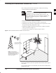
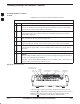
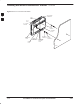
1 (See Figure 6) Identify a wall location where signal strength is optimum.
Use an extension cord to reach an AC power outlet if necessary.
2 Mark two mounting hole locations on the wall. The center line must be
148 mm (5–13/16”) apart and must be on a level plane.
3 If not using anchors, drill two 3 mm (1/8”) holes in the wood.
Continue with Step 4.
If using anchors, drill two 7 mm (9/32”) holes at the marked location.
Insert the anchors into the holes and tap the anchor heads flush against
the wall.
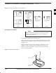
4 Install the mounting screws but do not screw in all the way. Leave 3 mm
(1/8”) space between the screw head and the wall (See Figure 11).
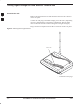
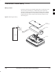
5 If included, install the backup battery in the battery compartment
accessed by removing the battery access door from the FWT. Reinstall
the battery access door (see page 2-11).
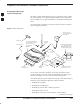
6 Locate the two adhesive–backed rubber mounting pads from the
hardware packet. Remove the backing and seat the pads in the two round
feet on the base of the FWT. Press firmly to ensure the pads adhere to
the surface.
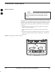
7 Plug in the RJ–11 connector and the wall cube connector and route the
cords in a manner similar to that shown in Figure 11. Slip the cords into
the cord retainer grooves.
8 Screw the antenna (or the cable’s antenna connector for optional external
mount antenna) into the TNC connector on the rear panel (see Figure 11).
9 Install the FWT onto the screws so that the unit is firmly seated.
2