
Installation Manual

Installing Desktop Fixed Wireless Terminal
Fixed Wireless Terminal Description and Installation
4/98
2-12
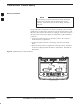
Installing the FWT on a desk
or table
Install the FWT on a desk or table as described in Table 4.
Table 4: Installing the FWT on a desktop or tabletop
n Step Action
1 Locate the two adhesive–backed rubber mounting pads from the hardware packet.
Remove the backing and seat the pads in the two round feet on the base of the FWT.
Press firmly to ensure the pads adhere to the surface.
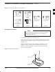
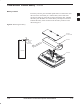
2 If included, install the backup battery in the battery compartment accessed by
removing the battery access door from the FWT. Reinstall the battery access door
(illustrated in Figure 9).
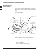
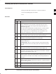
3 Screw the antenna (or antenna connector for optional external mount antenna) into the
TNC connector on the rear panel (see Figure 10 ).
4 Plug the telephone cord into the RJ–11 socket on the back of the FWT. (Shown in
Figure 10). Plug the 12 VDC connector into the DC power connector on the FWT.
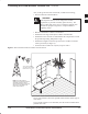
5 Position the FWT on a table or desk where signal strength is optimum. Plug the wall
cube into the AC power outlet. Use an extension cord to reach an AC power outlet if
necessary.
6 Check for the correct power and service LED indications (see Table 3 on page 2-7).
NOTE
With the FWT assembled and powered up, perform the Signal Strength Test described
on page 2-7 to confirm proper operation.
The FWT antenna should NOT be installed where it would be within a few inches of a
location where people normally stand, sit, or rest.
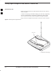
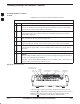
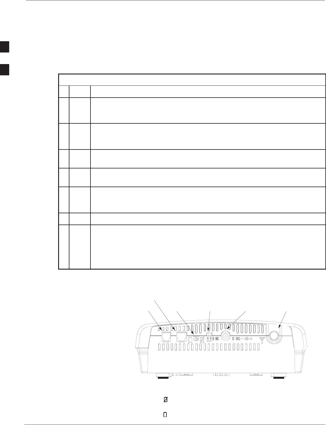
Figure 10: FWT Rear Panel
RJ–11
SOCKET
BATTERY
TOGGLE
SWITCH
AUXILIARY POWER
12 VDC SOCKET
ANTENNA TNC
CONNECTOR
WALL CUBE
12 VDC SOCKET
RJ–45 FOR DIGITAL
DATA APPLICATIONS
A battery toggle switch is provided on the back of the FWT. Set the
switch off (
) to disable the internal battery and conserve battery power
during an extended AC power outage. In normal operation, set the
switch on (
). The battery will recharge in either position.
2