
User's Manual

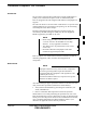
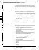
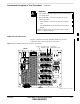

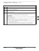
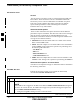

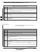
Table Of Contents
- Chapter 4: Acceptance Test Procedures
- Automated Acceptance Test Procedure
- Acceptance Tests - Test Set-up
- Abbreviated (All-inclusive) Acceptance Tests
- Individual Acceptance Tests
- TX Spectral Purity Transmit Mask Acceptance Test
- TX Waveform Quality (Rho) Acceptance Test
- TX Pilot Time Offset Acceptance Test
- TX Code Domain Power/Noise Floor Acceptance Test
- RX FER Acceptance Test
- Generating an ATP Report
- Updating Calibration Data Files
- Chapter 5: Prepare to Leave the Site
- Chapter 6: Troubleshooting
- Basic Troubleshooting: Overview
- Troubleshooting: Installation
- Cannot Log into Cell-Site
- Force LAN A Active (LMF Connection at I/O Panel LAN Connector)
- Force LAN A Active (LMF Connection at Service Shelf LAN Connector)
- Set the GLI IP Address
- Cannot Communicate with Power Meter
- Cannot Communicate with Communications System Analyzer
- Cannot Communicate with Signal Generator
- Troubleshooting: Download
- Troubleshooting: Calibration
- Basic Troubleshooting: RF Path Fault Isolation
- Troubleshooting: Transmit ATP
- Troubleshooting: Receive ATP
- Troubleshooting: CSM Checklist
- Troubleshooting: SCCP Backplane
- Troubleshooting: RFDS
- Module Front Panel LED Indicators and Connectors
- Troubleshooting: Span Control Link
- Appendix A: Data Sheets
- Appendix B: PN Offset/I & Q Offset Register Programming Information
- Appendix C: FRU Optimization / ATP Test Matrix
- Appendix D: BBX Gain Set Point vs. BTS Output
- Appendix E: CDMA Operating Frequency Programming Information
- Appendix F: Test Equipment Preparation
- Test Equipment Preparation
- Verifying and Setting GPIB Addresses
- Agilent E4406A Transmitter Tester GPIB Address
- Agilent E4432B Signal Generator GPIB Address
- Advantest R3267 Spectrum Analyzer GPIB Address
- Advantest R3562 Signal Generator GPIB Address
- Agilent 8935 Series E6380 (formerly HP 8935) Test Set GPIB Address
- Hewlett Packard HP 8921A and HP83236A/B GPIB Address
- Advantest R3465 Communications Test Set GPIB Address
- Motorola CyberTest GPIB Address
- HP 437 Power Meter GPIB Address
- Gigatronics 8541C Power Meter GPIB Address
- RS232 GPIB Interface Adapter
- Test Equipment Inter-Unit Connection, Testing, and Control
- Inter-Unit Connection, Testing, and Control Settings
- HP 8921A with PCS Interface Test Equipment Connections
- HP 8921A with PCS Interface System Connectivity Test
- Pretest Set-up for HP 8921A
- Pretest Set-up for Agilent 8935
- Advantest R3465 Connection
- R3465 GPIB Clock Set-up
- Pretest Set-up for Advantest R3465
- Agilent 8932/E4432B Test Equipment Interconnection
- Agilent E4406A/E4432B Test Equipment Interconnection
- Advantest R3267/R3562 Test Equipment Interconnection
- Equipment Calibration
- Manual Cable Calibration
- Appendix G: Downloading ROM Code
- Appendix H: In-Service Calibration
- Appendix I: Packet Backhaul Configuration
- BTS Router Initial Configuration
- Terminal Setup
- Downloading Minimum Canned BTS Router Configuration Files
- Verifying IOS Canned Version of the CF Memory Card
- Replacing Installed BTS Router CF Memory Card IOS Version
- Background
- Equipment and Software Required for Verification Methods
- Required Publications
- Method 1: Replacement of Installed Router CF Card IOS Data
- Method 2: Using a CF Memory Card Reader for Replacement of Installed IOS Version and Changing File Sequence ...
- Change CF Memory Card File Sequence to Place IOS File First on the Card
- Verify and Upgrade ROMMON Version
- Recovery from BTS Router Boot to ROMMON
- Entering or Changing Router FE Interface IP Address
- Preparation for Site Turn-over
- Index

Abbreviated (All–inclusive) Acceptance Tests – continued
FEB 2005 1X SC 4812T Lite BTS Optimization/ATP 4-7
PRELIMINARY
Table 4-2: All TX/RX Acceptance Test Procedure
n ActionStep
2 Select the BBX Cards and MCC Cards to be tested.
3 Click on Tests in the BTS Menu Bar, and select All TX/RX ATP... from the Pull–down Menu.
4 Select the appropriate carrier(s) and sector(s) (carrier-bts#-sector#-carrier#) from those displayed
in the Channels/Carrier Pick List.
NOTE
To select multiple items, hold down the Shift or Ctrl Key while clicking on Pick List Items to
select multiple carrier(s)–sector(s).
5 Verify that the correct Channel Number for the selected carrier is shown in the Carrier #
Channels Box.
– If it is not, obtain the latest bts–#.cdf (or bts–#.necf) and cbsc–#.CDF Files from the CBSC.
NOTE
If necessary, the correct Channel Number may be manually entered into the Carrier # Channels
Box.
6 Select the appropriate RX Branch (BOTH, MAIN, or DIVersity) in the Pull–down Menu.
* IMPORTANT
The RX Main and Diversity Paths must be tested separately for this configuration because each
requires a different Multi–Coupler Preselector type to provide the proper Test Signal Gain.
NOTE
If a Companion Frame with the Inter–frame Diversity RX Cabling disconnected is being tested do
not select BOTH in this step.
7 In the Rate Set Box, select the appropriate Data Rate (1=9600 3=9600 1X) from the Pull–down
Menu.
NOTE
The Rate Set selection of 3 is only available if 1X Cards are selected for the test.
8 Enter the Channel Elements to be tested for the RX ATP in the Channel Element(s) Box.
– By default, all Channel Elements are specified.
– The Channel Element Numbers are 0.based; therefore, the first Channel Element is 0.
NOTE
Use one of the following methods to enter more than one Channel Element:
– Enter non–sequential Channel Elements separated by a comma and no spaces (for example;
0,5,15).
– Enter a range of sequential Channel Elements by typing the first and last Channel Elements
separated by two periods (for example; 0..15).
table continued on next page
4