
User's Manual
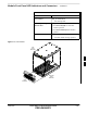
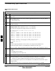
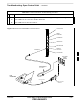


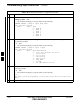
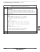


Table Of Contents
- Chapter 4: Acceptance Test Procedures
- Automated Acceptance Test Procedure
- Acceptance Tests - Test Set-up
- Abbreviated (All-inclusive) Acceptance Tests
- Individual Acceptance Tests
- TX Spectral Purity Transmit Mask Acceptance Test
- TX Waveform Quality (Rho) Acceptance Test
- TX Pilot Time Offset Acceptance Test
- TX Code Domain Power/Noise Floor Acceptance Test
- RX FER Acceptance Test
- Generating an ATP Report
- Updating Calibration Data Files
- Chapter 5: Prepare to Leave the Site
- Chapter 6: Troubleshooting
- Basic Troubleshooting: Overview
- Troubleshooting: Installation
- Cannot Log into Cell-Site
- Force LAN A Active (LMF Connection at I/O Panel LAN Connector)
- Force LAN A Active (LMF Connection at Service Shelf LAN Connector)
- Set the GLI IP Address
- Cannot Communicate with Power Meter
- Cannot Communicate with Communications System Analyzer
- Cannot Communicate with Signal Generator
- Troubleshooting: Download
- Troubleshooting: Calibration
- Basic Troubleshooting: RF Path Fault Isolation
- Troubleshooting: Transmit ATP
- Troubleshooting: Receive ATP
- Troubleshooting: CSM Checklist
- Troubleshooting: SCCP Backplane
- Troubleshooting: RFDS
- Module Front Panel LED Indicators and Connectors
- Troubleshooting: Span Control Link
- Appendix A: Data Sheets
- Appendix B: PN Offset/I & Q Offset Register Programming Information
- Appendix C: FRU Optimization / ATP Test Matrix
- Appendix D: BBX Gain Set Point vs. BTS Output
- Appendix E: CDMA Operating Frequency Programming Information
- Appendix F: Test Equipment Preparation
- Test Equipment Preparation
- Verifying and Setting GPIB Addresses
- Agilent E4406A Transmitter Tester GPIB Address
- Agilent E4432B Signal Generator GPIB Address
- Advantest R3267 Spectrum Analyzer GPIB Address
- Advantest R3562 Signal Generator GPIB Address
- Agilent 8935 Series E6380 (formerly HP 8935) Test Set GPIB Address
- Hewlett Packard HP 8921A and HP83236A/B GPIB Address
- Advantest R3465 Communications Test Set GPIB Address
- Motorola CyberTest GPIB Address
- HP 437 Power Meter GPIB Address
- Gigatronics 8541C Power Meter GPIB Address
- RS232 GPIB Interface Adapter
- Test Equipment Inter-Unit Connection, Testing, and Control
- Inter-Unit Connection, Testing, and Control Settings
- HP 8921A with PCS Interface Test Equipment Connections
- HP 8921A with PCS Interface System Connectivity Test
- Pretest Set-up for HP 8921A
- Pretest Set-up for Agilent 8935
- Advantest R3465 Connection
- R3465 GPIB Clock Set-up
- Pretest Set-up for Advantest R3465
- Agilent 8932/E4432B Test Equipment Interconnection
- Agilent E4406A/E4432B Test Equipment Interconnection
- Advantest R3267/R3562 Test Equipment Interconnection
- Equipment Calibration
- Manual Cable Calibration
- Appendix G: Downloading ROM Code
- Appendix H: In-Service Calibration
- Appendix I: Packet Backhaul Configuration
- BTS Router Initial Configuration
- Terminal Setup
- Downloading Minimum Canned BTS Router Configuration Files
- Verifying IOS Canned Version of the CF Memory Card
- Replacing Installed BTS Router CF Memory Card IOS Version
- Background
- Equipment and Software Required for Verification Methods
- Required Publications
- Method 1: Replacement of Installed Router CF Card IOS Data
- Method 2: Using a CF Memory Card Reader for Replacement of Installed IOS Version and Changing File Sequence ...
- Change CF Memory Card File Sequence to Place IOS File First on the Card
- Verify and Upgrade ROMMON Version
- Recovery from BTS Router Boot to ROMMON
- Entering or Changing Router FE Interface IP Address
- Preparation for Site Turn-over
- Index

Troubleshooting: Span Control Link – continued
6-44 1X SC 4812T Lite BTS Optimization/ATP FEB 2005
PRELIMINARY
Set BTS Site Span
Configuration
Perform the following procedure ONLY if Span
Configurations loaded in the MGLI3/GLI3s do not match
those in the OMC–R/CBSC database, AND ONLY when
the exact Configuration Data is available.
Loading incorrect Span Configuration Data will render the
site inoperable.
NOTE
Table 6-48: Set BTS Span Parameter Configuration Procedure
n Step Action
1 If not previously done, connect the LMF Computer to the MMI Port on the applicable
MGLI3/GLI3 as shown in Figure 6-6.
2 If there is no MMI Communication Session in progress with the applicable MGLI3/GLI3, initiate
one by using the Windows Desktop Shortcut Icon.
– Refer to Table 3-14.
3 At the GLI3> Prompt, enter the following command
GLI3>config ni format <option> <cr>
– The terminal will display a response similar to the following:
COMMAND SYNTAX: config ni format option
Next available options:
LIST – option : Span Option
E1_1 : E1_1 – E1 HDB3 CRC4 no TS16
E1_2 : E1_2 – E1 HDB3 no CRC4 no TS16
E1_3 : E1_3 – E1 HDB3 CRC4 TS16
E1_4 : E1_4 – E1 HDB3 no CRC4 TS16
T1_1 : T1_1 – D4, AMI, No ZCS
T1_2 : T1_2 – ESF, B8ZS
J1_1 : J1_1 – ESF, B8ZS (Japan) – Default
J1_2 : J1_2 – ESF, B8ZS
T1_3 : T1_3 – D4, AMI, ZCS>
NOTE
With this command, all active (in–use) Spans will be set to the same format.
table continued on next page
6