
User's Manual
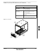
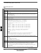
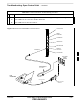


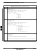
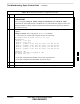


Table Of Contents
- Chapter 4: Acceptance Test Procedures
- Automated Acceptance Test Procedure
- Acceptance Tests - Test Set-up
- Abbreviated (All-inclusive) Acceptance Tests
- Individual Acceptance Tests
- TX Spectral Purity Transmit Mask Acceptance Test
- TX Waveform Quality (Rho) Acceptance Test
- TX Pilot Time Offset Acceptance Test
- TX Code Domain Power/Noise Floor Acceptance Test
- RX FER Acceptance Test
- Generating an ATP Report
- Updating Calibration Data Files
- Chapter 5: Prepare to Leave the Site
- Chapter 6: Troubleshooting
- Basic Troubleshooting: Overview
- Troubleshooting: Installation
- Cannot Log into Cell-Site
- Force LAN A Active (LMF Connection at I/O Panel LAN Connector)
- Force LAN A Active (LMF Connection at Service Shelf LAN Connector)
- Set the GLI IP Address
- Cannot Communicate with Power Meter
- Cannot Communicate with Communications System Analyzer
- Cannot Communicate with Signal Generator
- Troubleshooting: Download
- Troubleshooting: Calibration
- Basic Troubleshooting: RF Path Fault Isolation
- Troubleshooting: Transmit ATP
- Troubleshooting: Receive ATP
- Troubleshooting: CSM Checklist
- Troubleshooting: SCCP Backplane
- Troubleshooting: RFDS
- Module Front Panel LED Indicators and Connectors
- Troubleshooting: Span Control Link
- Appendix A: Data Sheets
- Appendix B: PN Offset/I & Q Offset Register Programming Information
- Appendix C: FRU Optimization / ATP Test Matrix
- Appendix D: BBX Gain Set Point vs. BTS Output
- Appendix E: CDMA Operating Frequency Programming Information
- Appendix F: Test Equipment Preparation
- Test Equipment Preparation
- Verifying and Setting GPIB Addresses
- Agilent E4406A Transmitter Tester GPIB Address
- Agilent E4432B Signal Generator GPIB Address
- Advantest R3267 Spectrum Analyzer GPIB Address
- Advantest R3562 Signal Generator GPIB Address
- Agilent 8935 Series E6380 (formerly HP 8935) Test Set GPIB Address
- Hewlett Packard HP 8921A and HP83236A/B GPIB Address
- Advantest R3465 Communications Test Set GPIB Address
- Motorola CyberTest GPIB Address
- HP 437 Power Meter GPIB Address
- Gigatronics 8541C Power Meter GPIB Address
- RS232 GPIB Interface Adapter
- Test Equipment Inter-Unit Connection, Testing, and Control
- Inter-Unit Connection, Testing, and Control Settings
- HP 8921A with PCS Interface Test Equipment Connections
- HP 8921A with PCS Interface System Connectivity Test
- Pretest Set-up for HP 8921A
- Pretest Set-up for Agilent 8935
- Advantest R3465 Connection
- R3465 GPIB Clock Set-up
- Pretest Set-up for Advantest R3465
- Agilent 8932/E4432B Test Equipment Interconnection
- Agilent E4406A/E4432B Test Equipment Interconnection
- Advantest R3267/R3562 Test Equipment Interconnection
- Equipment Calibration
- Manual Cable Calibration
- Appendix G: Downloading ROM Code
- Appendix H: In-Service Calibration
- Appendix I: Packet Backhaul Configuration
- BTS Router Initial Configuration
- Terminal Setup
- Downloading Minimum Canned BTS Router Configuration Files
- Verifying IOS Canned Version of the CF Memory Card
- Replacing Installed BTS Router CF Memory Card IOS Version
- Background
- Equipment and Software Required for Verification Methods
- Required Publications
- Method 1: Replacement of Installed Router CF Card IOS Data
- Method 2: Using a CF Memory Card Reader for Replacement of Installed IOS Version and Changing File Sequence ...
- Change CF Memory Card File Sequence to Place IOS File First on the Card
- Verify and Upgrade ROMMON Version
- Recovery from BTS Router Boot to ROMMON
- Entering or Changing Router FE Interface IP Address
- Preparation for Site Turn-over
- Index

Troubleshooting: Span Control Link
6-42 1X SC 4812T Lite BTS Optimization/ATP FEB 2005
PRELIMINARY
Span Problems (No Control
Link)
Table 6-47: Control Link Failure Troubleshooting Procedure
n Step Action
1 Connect the LMF Computer to the MMI Port on the applicable MGLI3/GLI3 as shown in
Figure 6-6.
2 Start an MMI Communication Session with the applicable MGLI3/GLI3 by using the Windows
Desktop Shortcut Icon.
– Refer to Table 3-14.
3 Once the connection window opens, press the LMF Computer Enter Key until the GLI3>
Prompt is obtained.
4
At the GLI3> Prompt, enter:
config ni current <cr> (equivalent of Span view command)
The system will respond with a display similar to the following:
The frame format in flash is set to use T1_2.
Equalization:
Span A – Default (0–131 feet for T1/J1, 120 Ohm for E1)
Span B – Default (0–131 feet for T1/J1, 120 Ohm for E1)
Span C – Default (0–131 feet for T1/J1, 120 Ohm for E1)
Span D – Default (0–131 feet for T1/J1, 120 Ohm for E1)
Span E – Default (0–131 feet for T1/J1, 120 Ohm for E1)
Span F – Default (0–131 feet for T1/J1, 120 Ohm for E1)
Linkspeed: Default (56K for T1 D4 AMI, 64K otherwise)
Currently, the link is running at the default rate
The actual rate is 0
NOTE
Defaults for Span Equalization are 0–131 feet for T1/J1 Spans and 120 Ohm for E1.
Default Link Speed is 56K for T1 D4 AMI Spans and 64K for all other types.
There is no need to change from defaults unless the OMC–R/CBSC Span Configuration requires it.
5 The Span Configurations loaded in the GLI must match those in the OMC–R/CBSC Database for
the BTS.
S If they do, proceed to Step 6.
S If they do not, proceed to Table 6-48.
6 Repeat Steps 1 through 5 for all remaining GLI Cards.
7 If the Span Settings are correct, verify the EDLC Parameters using the show Command.
– Check for any Alarm Conditions that indicate the Span is not operating correctly.
S Try looping back the Span Line from the DSX Panel to the MM, and verify that the looped
signal is good.
S Listen for a Control Tone on the appropriate Timeslot from the Base Site and MM.
table continued on next page
6