
User's Manual


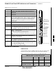
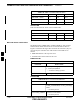
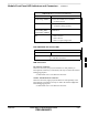

Table Of Contents
- Chapter 4: Acceptance Test Procedures
- Automated Acceptance Test Procedure
- Acceptance Tests - Test Set-up
- Abbreviated (All-inclusive) Acceptance Tests
- Individual Acceptance Tests
- TX Spectral Purity Transmit Mask Acceptance Test
- TX Waveform Quality (Rho) Acceptance Test
- TX Pilot Time Offset Acceptance Test
- TX Code Domain Power/Noise Floor Acceptance Test
- RX FER Acceptance Test
- Generating an ATP Report
- Updating Calibration Data Files
- Chapter 5: Prepare to Leave the Site
- Chapter 6: Troubleshooting
- Basic Troubleshooting: Overview
- Troubleshooting: Installation
- Cannot Log into Cell-Site
- Force LAN A Active (LMF Connection at I/O Panel LAN Connector)
- Force LAN A Active (LMF Connection at Service Shelf LAN Connector)
- Set the GLI IP Address
- Cannot Communicate with Power Meter
- Cannot Communicate with Communications System Analyzer
- Cannot Communicate with Signal Generator
- Troubleshooting: Download
- Troubleshooting: Calibration
- Basic Troubleshooting: RF Path Fault Isolation
- Troubleshooting: Transmit ATP
- Troubleshooting: Receive ATP
- Troubleshooting: CSM Checklist
- Troubleshooting: SCCP Backplane
- Troubleshooting: RFDS
- Module Front Panel LED Indicators and Connectors
- Troubleshooting: Span Control Link
- Appendix A: Data Sheets
- Appendix B: PN Offset/I & Q Offset Register Programming Information
- Appendix C: FRU Optimization / ATP Test Matrix
- Appendix D: BBX Gain Set Point vs. BTS Output
- Appendix E: CDMA Operating Frequency Programming Information
- Appendix F: Test Equipment Preparation
- Test Equipment Preparation
- Verifying and Setting GPIB Addresses
- Agilent E4406A Transmitter Tester GPIB Address
- Agilent E4432B Signal Generator GPIB Address
- Advantest R3267 Spectrum Analyzer GPIB Address
- Advantest R3562 Signal Generator GPIB Address
- Agilent 8935 Series E6380 (formerly HP 8935) Test Set GPIB Address
- Hewlett Packard HP 8921A and HP83236A/B GPIB Address
- Advantest R3465 Communications Test Set GPIB Address
- Motorola CyberTest GPIB Address
- HP 437 Power Meter GPIB Address
- Gigatronics 8541C Power Meter GPIB Address
- RS232 GPIB Interface Adapter
- Test Equipment Inter-Unit Connection, Testing, and Control
- Inter-Unit Connection, Testing, and Control Settings
- HP 8921A with PCS Interface Test Equipment Connections
- HP 8921A with PCS Interface System Connectivity Test
- Pretest Set-up for HP 8921A
- Pretest Set-up for Agilent 8935
- Advantest R3465 Connection
- R3465 GPIB Clock Set-up
- Pretest Set-up for Advantest R3465
- Agilent 8932/E4432B Test Equipment Interconnection
- Agilent E4406A/E4432B Test Equipment Interconnection
- Advantest R3267/R3562 Test Equipment Interconnection
- Equipment Calibration
- Manual Cable Calibration
- Appendix G: Downloading ROM Code
- Appendix H: In-Service Calibration
- Appendix I: Packet Backhaul Configuration
- BTS Router Initial Configuration
- Terminal Setup
- Downloading Minimum Canned BTS Router Configuration Files
- Verifying IOS Canned Version of the CF Memory Card
- Replacing Installed BTS Router CF Memory Card IOS Version
- Background
- Equipment and Software Required for Verification Methods
- Required Publications
- Method 1: Replacement of Installed Router CF Card IOS Data
- Method 2: Using a CF Memory Card Reader for Replacement of Installed IOS Version and Changing File Sequence ...
- Change CF Memory Card File Sequence to Place IOS File First on the Card
- Verify and Upgrade ROMMON Version
- Recovery from BTS Router Boot to ROMMON
- Entering or Changing Router FE Interface IP Address
- Preparation for Site Turn-over
- Index

Module Front Panel LED Indicators and Connectors – continued
FEB 2005 1X SC 4812T Lite BTS Optimization/ATP 6-37
PRELIMINARY
STATUS OFF − operating normally .
ON − briefly during powerup when the Alarm LED turns OFF.
SLOW GREEN − when the GLI3 is INS (inservice).
RESET
ALARM OFF − operating normally.
ON − briefly during powerup when the Alarm LED turns OFF.
SLOW GREEN − when the GLI3 is INS (inservice).
BPR A
Span
ACTIVE
LED OPERATING STATUS
Pressing and releasing the switc h resets all functions on the GLI3.
Shows the operating status of the redundant cards. The redundant
card toggles automatically if the active card is removed or fails.
ON − active card operating normally .
OFF − standby card operating normally.
Connects to either a BPR or Expan sion Cage and is wired as an
Ethernet hub.
An RS232, serial, asynchronous communications link for use as
an MMI port. This port supports 300 baud, up to a maximum of
115,200 baud communications.
BPR B
GLI
AUX
Supports the cross−coupled Ethernet circuits to the Mate GLI using a
standard Ethernet straight cable.
Wired as an Ethernet hub for direct connection to a personal comput
er with a standard Ethernet cable. It allows connection of an Ethernet
sniffer" when the Ethernet switch is properly configured for port mon
itoring. This port may also be connected to the optional Motorola
MOSCAD−L Network Fault Management unit using a Crosso ver
Ethernet cable.
Connects to either a BPR or Expan sion Cage and is wired as an
Ethernet hub.
MMI Port
Reset Switch
Dual 100BASE–T
in a single RJ45
to Redundant
(Mate) GLI3
100BASE–T
Auxiliary Monitor
Port
BPR B AUX RESET
SPAN
ALARM
MMI
ACT
STA
100BASE–T to
BTS Packet Router
or Expansion Port
Span (LED)
Alarm (LED)
Active (LED)
Status (LED)
GLIBPR A
ti-CDMA-WP-00064-v01-ildoc-ftw
OFF − card is powered down, in initialization, or in standby.
GREEN − operating normally.
YELLOW − one or more of the equipped initialized spans is receiving
a remote alarm indication signal from the far end.
RED − one or more of the equipped initialized spans is in an alarm
state.
MMI
Figure 6-3: GLI3 Front Panel
BBX LED Status Combinations
PWR/ALM LED
All Broadband Transceiver (BBX) Cards have their own Alarm (Fault)
Detection Circuitry that controls the state of the PWR/ALM LED.
Table 6-41 describes the states of the bi-color PWR/ALM LED.
Table 6-41: BBX Card PWR/ALM LED States
Physical and Alarm State Off Red Green
Microprocessor in Reset ––– Continuous –––
OOS–ROM – No alarm 1.4s ––– 0.2s
OOS–ROM – Alarm ––– 1.4s 0.2s
OOS–RAM – No alarm 0.2s ––– 0.2s
6