
User's Manual

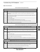
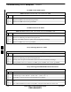


Table Of Contents
- Chapter 4: Acceptance Test Procedures
- Automated Acceptance Test Procedure
- Acceptance Tests - Test Set-up
- Abbreviated (All-inclusive) Acceptance Tests
- Individual Acceptance Tests
- TX Spectral Purity Transmit Mask Acceptance Test
- TX Waveform Quality (Rho) Acceptance Test
- TX Pilot Time Offset Acceptance Test
- TX Code Domain Power/Noise Floor Acceptance Test
- RX FER Acceptance Test
- Generating an ATP Report
- Updating Calibration Data Files
- Chapter 5: Prepare to Leave the Site
- Chapter 6: Troubleshooting
- Basic Troubleshooting: Overview
- Troubleshooting: Installation
- Cannot Log into Cell-Site
- Force LAN A Active (LMF Connection at I/O Panel LAN Connector)
- Force LAN A Active (LMF Connection at Service Shelf LAN Connector)
- Set the GLI IP Address
- Cannot Communicate with Power Meter
- Cannot Communicate with Communications System Analyzer
- Cannot Communicate with Signal Generator
- Troubleshooting: Download
- Troubleshooting: Calibration
- Basic Troubleshooting: RF Path Fault Isolation
- Troubleshooting: Transmit ATP
- Troubleshooting: Receive ATP
- Troubleshooting: CSM Checklist
- Troubleshooting: SCCP Backplane
- Troubleshooting: RFDS
- Module Front Panel LED Indicators and Connectors
- Troubleshooting: Span Control Link
- Appendix A: Data Sheets
- Appendix B: PN Offset/I & Q Offset Register Programming Information
- Appendix C: FRU Optimization / ATP Test Matrix
- Appendix D: BBX Gain Set Point vs. BTS Output
- Appendix E: CDMA Operating Frequency Programming Information
- Appendix F: Test Equipment Preparation
- Test Equipment Preparation
- Verifying and Setting GPIB Addresses
- Agilent E4406A Transmitter Tester GPIB Address
- Agilent E4432B Signal Generator GPIB Address
- Advantest R3267 Spectrum Analyzer GPIB Address
- Advantest R3562 Signal Generator GPIB Address
- Agilent 8935 Series E6380 (formerly HP 8935) Test Set GPIB Address
- Hewlett Packard HP 8921A and HP83236A/B GPIB Address
- Advantest R3465 Communications Test Set GPIB Address
- Motorola CyberTest GPIB Address
- HP 437 Power Meter GPIB Address
- Gigatronics 8541C Power Meter GPIB Address
- RS232 GPIB Interface Adapter
- Test Equipment Inter-Unit Connection, Testing, and Control
- Inter-Unit Connection, Testing, and Control Settings
- HP 8921A with PCS Interface Test Equipment Connections
- HP 8921A with PCS Interface System Connectivity Test
- Pretest Set-up for HP 8921A
- Pretest Set-up for Agilent 8935
- Advantest R3465 Connection
- R3465 GPIB Clock Set-up
- Pretest Set-up for Advantest R3465
- Agilent 8932/E4432B Test Equipment Interconnection
- Agilent E4406A/E4432B Test Equipment Interconnection
- Advantest R3267/R3562 Test Equipment Interconnection
- Equipment Calibration
- Manual Cable Calibration
- Appendix G: Downloading ROM Code
- Appendix H: In-Service Calibration
- Appendix I: Packet Backhaul Configuration
- BTS Router Initial Configuration
- Terminal Setup
- Downloading Minimum Canned BTS Router Configuration Files
- Verifying IOS Canned Version of the CF Memory Card
- Replacing Installed BTS Router CF Memory Card IOS Version
- Background
- Equipment and Software Required for Verification Methods
- Required Publications
- Method 1: Replacement of Installed Router CF Card IOS Data
- Method 2: Using a CF Memory Card Reader for Replacement of Installed IOS Version and Changing File Sequence ...
- Change CF Memory Card File Sequence to Place IOS File First on the Card
- Verify and Upgrade ROMMON Version
- Recovery from BTS Router Boot to ROMMON
- Entering or Changing Router FE Interface IP Address
- Preparation for Site Turn-over
- Index

Troubleshooting: RFDS
FEB 2005 1X SC 4812T Lite BTS Optimization/ATP 6-29
PRELIMINARY
Introduction
The RFDS is used to perform Pre–Calibration Verification and
Post-Calibration Audits that limit-check the RFDS-generate and
reported Receive Levels of every path from the RFDS through the
Directional Coupler Coupled Paths. In the event of test failure, refer to
the following tables.
All Tests Fail
Table 6-31: RFDS Fault Isolation – All Tests Fail Troubleshooting Procedure
Step Action
1 Check the TX Calibration Equipment for proper operation by performing the following actions.
1a Manually set the Signal Generator Output Attenuator to the lowest Output Power Setting.
1b Connect the Output Port to the Spectrum Analyzer RF Input Port.
2 Set the Signal Generator Output Attenuator to –90 dBm, and switch on the RF Output.
3 Verify that the Spectrum Analyzer can do the following:
– Receive the signal.
– Indicate the correct Signal Strength (accounting for the Cable Insertion Loss).
– Indicate the approximate frequency.
4 Visually inspect the RF Cabling.
Make sure that the Directional Coupler Forward Port and Reflected Port are connected to the RFDS
Antenna Select Unit on the RFDS.
5 Check the wiring against the Site Documentation Wiring Diagram or the 1X SC4812T Lite Hardware
Installation manual (68P09262A57)
6 Verify that all changes to the RFDS Parameter Settings have been downloaded.
7 Status the TSU to verify that the TSIC and SUA Software Versions are correct.
8 Check to see that all RFDS Cards show green on the Front Panel LEDs.
9 Visually check for external damage.
10 If any card LEDs do not show green, replace the RFDS with a known–good unit.
– Re–test after replacement.
All RX and TX Paths Fail
If every Receive or Transmit Path fails, the problem most likely lies with
the RF Converter Card or the Transceiver Card. Replace the RFDS with
a known–good unit and retest.
6