
User's Manual

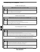


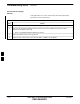
Table Of Contents
- Chapter 4: Acceptance Test Procedures
- Automated Acceptance Test Procedure
- Acceptance Tests - Test Set-up
- Abbreviated (All-inclusive) Acceptance Tests
- Individual Acceptance Tests
- TX Spectral Purity Transmit Mask Acceptance Test
- TX Waveform Quality (Rho) Acceptance Test
- TX Pilot Time Offset Acceptance Test
- TX Code Domain Power/Noise Floor Acceptance Test
- RX FER Acceptance Test
- Generating an ATP Report
- Updating Calibration Data Files
- Chapter 5: Prepare to Leave the Site
- Chapter 6: Troubleshooting
- Basic Troubleshooting: Overview
- Troubleshooting: Installation
- Cannot Log into Cell-Site
- Force LAN A Active (LMF Connection at I/O Panel LAN Connector)
- Force LAN A Active (LMF Connection at Service Shelf LAN Connector)
- Set the GLI IP Address
- Cannot Communicate with Power Meter
- Cannot Communicate with Communications System Analyzer
- Cannot Communicate with Signal Generator
- Troubleshooting: Download
- Troubleshooting: Calibration
- Basic Troubleshooting: RF Path Fault Isolation
- Troubleshooting: Transmit ATP
- Troubleshooting: Receive ATP
- Troubleshooting: CSM Checklist
- Troubleshooting: SCCP Backplane
- Troubleshooting: RFDS
- Module Front Panel LED Indicators and Connectors
- Troubleshooting: Span Control Link
- Appendix A: Data Sheets
- Appendix B: PN Offset/I & Q Offset Register Programming Information
- Appendix C: FRU Optimization / ATP Test Matrix
- Appendix D: BBX Gain Set Point vs. BTS Output
- Appendix E: CDMA Operating Frequency Programming Information
- Appendix F: Test Equipment Preparation
- Test Equipment Preparation
- Verifying and Setting GPIB Addresses
- Agilent E4406A Transmitter Tester GPIB Address
- Agilent E4432B Signal Generator GPIB Address
- Advantest R3267 Spectrum Analyzer GPIB Address
- Advantest R3562 Signal Generator GPIB Address
- Agilent 8935 Series E6380 (formerly HP 8935) Test Set GPIB Address
- Hewlett Packard HP 8921A and HP83236A/B GPIB Address
- Advantest R3465 Communications Test Set GPIB Address
- Motorola CyberTest GPIB Address
- HP 437 Power Meter GPIB Address
- Gigatronics 8541C Power Meter GPIB Address
- RS232 GPIB Interface Adapter
- Test Equipment Inter-Unit Connection, Testing, and Control
- Inter-Unit Connection, Testing, and Control Settings
- HP 8921A with PCS Interface Test Equipment Connections
- HP 8921A with PCS Interface System Connectivity Test
- Pretest Set-up for HP 8921A
- Pretest Set-up for Agilent 8935
- Advantest R3465 Connection
- R3465 GPIB Clock Set-up
- Pretest Set-up for Advantest R3465
- Agilent 8932/E4432B Test Equipment Interconnection
- Agilent E4406A/E4432B Test Equipment Interconnection
- Advantest R3267/R3562 Test Equipment Interconnection
- Equipment Calibration
- Manual Cable Calibration
- Appendix G: Downloading ROM Code
- Appendix H: In-Service Calibration
- Appendix I: Packet Backhaul Configuration
- BTS Router Initial Configuration
- Terminal Setup
- Downloading Minimum Canned BTS Router Configuration Files
- Verifying IOS Canned Version of the CF Memory Card
- Replacing Installed BTS Router CF Memory Card IOS Version
- Background
- Equipment and Software Required for Verification Methods
- Required Publications
- Method 1: Replacement of Installed Router CF Card IOS Data
- Method 2: Using a CF Memory Card Reader for Replacement of Installed IOS Version and Changing File Sequence ...
- Change CF Memory Card File Sequence to Place IOS File First on the Card
- Verify and Upgrade ROMMON Version
- Recovery from BTS Router Boot to ROMMON
- Entering or Changing Router FE Interface IP Address
- Preparation for Site Turn-over
- Index

Troubleshooting: SCCP Backplane – continued
FEB 2005 1X SC 4812T Lite BTS Optimization/ATP 6-25
PRELIMINARY
Digital Control Problems
No GLI Control via LMF (all GLI Cards)
Table 6-21: No GLI Control Through LMF (All GLI Cards)
n Step Action
1 Check the Ethernet LAN for proper connection, damage, shorts, or opens.
2 Ensure that the LAN IN and OUT Connectors in the Power Entry Compartment are properly
terminated.
3 Ensure that the proper IP Address is entered in the Network Login Tab of the LMF Login Screen.
4 Logout and exit from the LMF.
5 Restart the LMF.
6 Login to the BTS again.
7 Verify SCCP Backplane Shelf ID DIP Switch is set correctly.
8 Visually check the Master GLI Connectors (both card and backplane) for damage.
9 Replace the Master GLI with a known good GLI.
No GLI Control through Span Line Connection (All GLI Cards)
Table 6-22: No GLI Control Through Span Line Connection (Both GLI Cards)
n Step Action
1 Verify that the SCCP Backplane Shelf ID DIP Switch is set correctly.
2 Verify that the BTS and GLI Cards are correctly configured in the OMC–R/CBSC Database.
3 Verify that the Span Configurations set in the GLI Cards match those in the OMC–R/CBSC
Database.
– Refer to Table 6-47.
4 Visually check the Master GLI Connectors (both card and backplane) for damage.
5 Replace the Master GLI with a known good GLI.
6 Check the Span Line Cabling from the Punchblock to the Master GLI for proper connection and
damage.
Table 6-23: MGLI Control Good – No Control Over Co–located GLI
n Step Action
1 Verify that the BTS and GLIs are correctly configured in the OMC–R/CBSC Database.
2 Check the Ethernet Connections for proper connection, damage, shorts, or opens.
3 Visually check all GLI Connectors (both card and backplane) for damage.
4 Replace the remaining GLI with a known good GLI.
6