
User's Manual

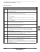
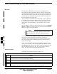


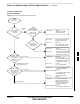


Table Of Contents
- Chapter 4: Acceptance Test Procedures
- Automated Acceptance Test Procedure
- Acceptance Tests - Test Set-up
- Abbreviated (All-inclusive) Acceptance Tests
- Individual Acceptance Tests
- TX Spectral Purity Transmit Mask Acceptance Test
- TX Waveform Quality (Rho) Acceptance Test
- TX Pilot Time Offset Acceptance Test
- TX Code Domain Power/Noise Floor Acceptance Test
- RX FER Acceptance Test
- Generating an ATP Report
- Updating Calibration Data Files
- Chapter 5: Prepare to Leave the Site
- Chapter 6: Troubleshooting
- Basic Troubleshooting: Overview
- Troubleshooting: Installation
- Cannot Log into Cell-Site
- Force LAN A Active (LMF Connection at I/O Panel LAN Connector)
- Force LAN A Active (LMF Connection at Service Shelf LAN Connector)
- Set the GLI IP Address
- Cannot Communicate with Power Meter
- Cannot Communicate with Communications System Analyzer
- Cannot Communicate with Signal Generator
- Troubleshooting: Download
- Troubleshooting: Calibration
- Basic Troubleshooting: RF Path Fault Isolation
- Troubleshooting: Transmit ATP
- Troubleshooting: Receive ATP
- Troubleshooting: CSM Checklist
- Troubleshooting: SCCP Backplane
- Troubleshooting: RFDS
- Module Front Panel LED Indicators and Connectors
- Troubleshooting: Span Control Link
- Appendix A: Data Sheets
- Appendix B: PN Offset/I & Q Offset Register Programming Information
- Appendix C: FRU Optimization / ATP Test Matrix
- Appendix D: BBX Gain Set Point vs. BTS Output
- Appendix E: CDMA Operating Frequency Programming Information
- Appendix F: Test Equipment Preparation
- Test Equipment Preparation
- Verifying and Setting GPIB Addresses
- Agilent E4406A Transmitter Tester GPIB Address
- Agilent E4432B Signal Generator GPIB Address
- Advantest R3267 Spectrum Analyzer GPIB Address
- Advantest R3562 Signal Generator GPIB Address
- Agilent 8935 Series E6380 (formerly HP 8935) Test Set GPIB Address
- Hewlett Packard HP 8921A and HP83236A/B GPIB Address
- Advantest R3465 Communications Test Set GPIB Address
- Motorola CyberTest GPIB Address
- HP 437 Power Meter GPIB Address
- Gigatronics 8541C Power Meter GPIB Address
- RS232 GPIB Interface Adapter
- Test Equipment Inter-Unit Connection, Testing, and Control
- Inter-Unit Connection, Testing, and Control Settings
- HP 8921A with PCS Interface Test Equipment Connections
- HP 8921A with PCS Interface System Connectivity Test
- Pretest Set-up for HP 8921A
- Pretest Set-up for Agilent 8935
- Advantest R3465 Connection
- R3465 GPIB Clock Set-up
- Pretest Set-up for Advantest R3465
- Agilent 8932/E4432B Test Equipment Interconnection
- Agilent E4406A/E4432B Test Equipment Interconnection
- Advantest R3267/R3562 Test Equipment Interconnection
- Equipment Calibration
- Manual Cable Calibration
- Appendix G: Downloading ROM Code
- Appendix H: In-Service Calibration
- Appendix I: Packet Backhaul Configuration
- BTS Router Initial Configuration
- Terminal Setup
- Downloading Minimum Canned BTS Router Configuration Files
- Verifying IOS Canned Version of the CF Memory Card
- Replacing Installed BTS Router CF Memory Card IOS Version
- Background
- Equipment and Software Required for Verification Methods
- Required Publications
- Method 1: Replacement of Installed Router CF Card IOS Data
- Method 2: Using a CF Memory Card Reader for Replacement of Installed IOS Version and Changing File Sequence ...
- Change CF Memory Card File Sequence to Place IOS File First on the Card
- Verify and Upgrade ROMMON Version
- Recovery from BTS Router Boot to ROMMON
- Entering or Changing Router FE Interface IP Address
- Preparation for Site Turn-over
- Index

Basic Troubleshooting: RF Path Fault Isolation
6-14 1X SC 4812T Lite BTS Optimization/ATP FEB 2005
PRELIMINARY
Overview
The Optimization (RF Path Characterization or Calibration) and
Post-Calibration (Audit) Procedures measure and limit-check the BTS
reported Transmit and Receive Levels of the path from each BBX to the
back of the frame. When a fault is detected, it is specific to a Receive or
Transmit Path. The Troubleshooting Process in this section determines
the most probable cause of the fault.
As the Calibration and Audit Tests are performed, results are displayed
in the LMF Test Status Report Window. When faults are encountered,
the Test Procedure in progress continues running and displaying any
further faults. If it appears that there are major faults, the test can be
aborted.
The test results can be saved to a
bts–#.rpt File in the<x>:\<lmf home
directory \cdma\bts–# Folder. To do this, close the Test Status Report
Window using the Save Results Button.
Closing the Test Status Report Window with the Dismiss
Button will delete the test results without saving them.
NOTE
If a test is re–run or a new calibration, audit, or test is run and the results
are saved, the previous test results in the bts–#.rpt File are
overwritten. To prevent losing previous test results in the bts–#.rpt
File, refer to the procedure in Table 4-10 before performing further
testing with the LMF.
If there are major faults, recheck the Test Equipment Attachments for
errors. If none are found, close the Test Status Report Window using the
Save Results Button, and save the contents of the resulting bts–#.rpt
file as described in Table 4-10. Also, note other specifics about the
failure, and proceed with the Fault Isolation Procedure.
If Every Test Fails
If all tests fail, perform the procedure in Table 6-14.
Table 6-14: All Tests Fail Troubleshooting Procedure
n Step Action
1 Check the Calibration Equipment for proper operation by manually setting the Signal Generator
Output Attenuator to the lowest Output Power Setting.
2 Connect the Output Port to the Spectrum Analyzer RF Input Port.
3 Set the Signal Generator Output Attenuator to –90 dBm, and switch on the RF Output.
4 Verify that the Spectrum Analyzer can receive the signal, indicate the correct Signal Strength
(accounting for the Cable Insertion Loss), and indicate the approximate frequency.
6