
User's Manual


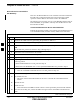
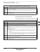

Table Of Contents
- Chapter 4: Acceptance Test Procedures
- Automated Acceptance Test Procedure
- Acceptance Tests - Test Set-up
- Abbreviated (All-inclusive) Acceptance Tests
- Individual Acceptance Tests
- TX Spectral Purity Transmit Mask Acceptance Test
- TX Waveform Quality (Rho) Acceptance Test
- TX Pilot Time Offset Acceptance Test
- TX Code Domain Power/Noise Floor Acceptance Test
- RX FER Acceptance Test
- Generating an ATP Report
- Updating Calibration Data Files
- Chapter 5: Prepare to Leave the Site
- Chapter 6: Troubleshooting
- Basic Troubleshooting: Overview
- Troubleshooting: Installation
- Cannot Log into Cell-Site
- Force LAN A Active (LMF Connection at I/O Panel LAN Connector)
- Force LAN A Active (LMF Connection at Service Shelf LAN Connector)
- Set the GLI IP Address
- Cannot Communicate with Power Meter
- Cannot Communicate with Communications System Analyzer
- Cannot Communicate with Signal Generator
- Troubleshooting: Download
- Troubleshooting: Calibration
- Basic Troubleshooting: RF Path Fault Isolation
- Troubleshooting: Transmit ATP
- Troubleshooting: Receive ATP
- Troubleshooting: CSM Checklist
- Troubleshooting: SCCP Backplane
- Troubleshooting: RFDS
- Module Front Panel LED Indicators and Connectors
- Troubleshooting: Span Control Link
- Appendix A: Data Sheets
- Appendix B: PN Offset/I & Q Offset Register Programming Information
- Appendix C: FRU Optimization / ATP Test Matrix
- Appendix D: BBX Gain Set Point vs. BTS Output
- Appendix E: CDMA Operating Frequency Programming Information
- Appendix F: Test Equipment Preparation
- Test Equipment Preparation
- Verifying and Setting GPIB Addresses
- Agilent E4406A Transmitter Tester GPIB Address
- Agilent E4432B Signal Generator GPIB Address
- Advantest R3267 Spectrum Analyzer GPIB Address
- Advantest R3562 Signal Generator GPIB Address
- Agilent 8935 Series E6380 (formerly HP 8935) Test Set GPIB Address
- Hewlett Packard HP 8921A and HP83236A/B GPIB Address
- Advantest R3465 Communications Test Set GPIB Address
- Motorola CyberTest GPIB Address
- HP 437 Power Meter GPIB Address
- Gigatronics 8541C Power Meter GPIB Address
- RS232 GPIB Interface Adapter
- Test Equipment Inter-Unit Connection, Testing, and Control
- Inter-Unit Connection, Testing, and Control Settings
- HP 8921A with PCS Interface Test Equipment Connections
- HP 8921A with PCS Interface System Connectivity Test
- Pretest Set-up for HP 8921A
- Pretest Set-up for Agilent 8935
- Advantest R3465 Connection
- R3465 GPIB Clock Set-up
- Pretest Set-up for Advantest R3465
- Agilent 8932/E4432B Test Equipment Interconnection
- Agilent E4406A/E4432B Test Equipment Interconnection
- Advantest R3267/R3562 Test Equipment Interconnection
- Equipment Calibration
- Manual Cable Calibration
- Appendix G: Downloading ROM Code
- Appendix H: In-Service Calibration
- Appendix I: Packet Backhaul Configuration
- BTS Router Initial Configuration
- Terminal Setup
- Downloading Minimum Canned BTS Router Configuration Files
- Verifying IOS Canned Version of the CF Memory Card
- Replacing Installed BTS Router CF Memory Card IOS Version
- Background
- Equipment and Software Required for Verification Methods
- Required Publications
- Method 1: Replacement of Installed Router CF Card IOS Data
- Method 2: Using a CF Memory Card Reader for Replacement of Installed IOS Version and Changing File Sequence ...
- Change CF Memory Card File Sequence to Place IOS File First on the Card
- Verify and Upgrade ROMMON Version
- Recovery from BTS Router Boot to ROMMON
- Entering or Changing Router FE Interface IP Address
- Preparation for Site Turn-over
- Index

Prepare to Leave the Site – continued
5-6 1X SC 4812T Lite BTS Optimization/ATP FEB 2005
PRELIMINARY
Reset All Devices and Initialize
Site Remotely
Devices in the BTS should not be left with Data and Code Loaded from
the LMF. The Configuration Data and Code Loads used for normal
operation could be different from those stored in the LMF Files.
The following two procedure, one for Circuit Backhaul and the other for
Packet Backhaul, are provided to remotely reset the BTS Devices and
then initialize the BTS.
Circuit Backhaul Remote Reset and Initialization
Perform the procedure in Table 5-6 to remotely reset the BTS Devices in
a Circuit Backhaul BTS, and then remotely initialize the same BTS.
Table 5-6: Circuit Backhaul Remote Reset and Initialization Procedure
n Step Action
1 Terminate the LMF Session by performing the procedure in Table 5-3.
2 Reconnect the Spans by performing the procedure in Table 5-4.
3 From the BTS Site, contact the OMC–R and request the operator to perform a BTS Reset.
OR
At the BTS Site, perform the actions in Step 4 through Step 6.
4 Unseat one GLI Card and wait for 30 seconds.
5 Re–seat the GLI and wait for it to complete its Initialization Process (this takes about one minute).
6 Repeat Step 4 and Step 5 for the second GLI.
7 Depending on the number and configuration of installed operational GLI Cards, perform the
following actions.
S BTS with Redundant GLI Cards, proceed to Step 8.
S BTS with a non–Redundant GLI or a non–operational Redundant GLI, proceed to Step 9.
8 From the OMC–R, run the ACTIVATE Command on the BTS.
– After the ACTIVATE Command has been executed, proceed to Step 10.
9 From the OMC–R, perform the following actions.
9a ACTIVATE the GLI.
– This action sets the NextLoad Attribute for the GLI to work with the current BSS Software
Version.
9b Disable the GLI.
9c Enable the GLI.
– This action allows the MM to load the software version specified by the NextLoad Attribute.
9d Once the GLI is INS_ACT, contact the OMC–R to again run the ACTIVATE Command on the
BTS.
table continued on next page
5