
User's Manual

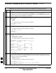
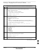

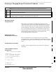
Table Of Contents
- Chapter 4: Acceptance Test Procedures
- Automated Acceptance Test Procedure
- Acceptance Tests - Test Set-up
- Abbreviated (All-inclusive) Acceptance Tests
- Individual Acceptance Tests
- TX Spectral Purity Transmit Mask Acceptance Test
- TX Waveform Quality (Rho) Acceptance Test
- TX Pilot Time Offset Acceptance Test
- TX Code Domain Power/Noise Floor Acceptance Test
- RX FER Acceptance Test
- Generating an ATP Report
- Updating Calibration Data Files
- Chapter 5: Prepare to Leave the Site
- Chapter 6: Troubleshooting
- Basic Troubleshooting: Overview
- Troubleshooting: Installation
- Cannot Log into Cell-Site
- Force LAN A Active (LMF Connection at I/O Panel LAN Connector)
- Force LAN A Active (LMF Connection at Service Shelf LAN Connector)
- Set the GLI IP Address
- Cannot Communicate with Power Meter
- Cannot Communicate with Communications System Analyzer
- Cannot Communicate with Signal Generator
- Troubleshooting: Download
- Troubleshooting: Calibration
- Basic Troubleshooting: RF Path Fault Isolation
- Troubleshooting: Transmit ATP
- Troubleshooting: Receive ATP
- Troubleshooting: CSM Checklist
- Troubleshooting: SCCP Backplane
- Troubleshooting: RFDS
- Module Front Panel LED Indicators and Connectors
- Troubleshooting: Span Control Link
- Appendix A: Data Sheets
- Appendix B: PN Offset/I & Q Offset Register Programming Information
- Appendix C: FRU Optimization / ATP Test Matrix
- Appendix D: BBX Gain Set Point vs. BTS Output
- Appendix E: CDMA Operating Frequency Programming Information
- Appendix F: Test Equipment Preparation
- Test Equipment Preparation
- Verifying and Setting GPIB Addresses
- Agilent E4406A Transmitter Tester GPIB Address
- Agilent E4432B Signal Generator GPIB Address
- Advantest R3267 Spectrum Analyzer GPIB Address
- Advantest R3562 Signal Generator GPIB Address
- Agilent 8935 Series E6380 (formerly HP 8935) Test Set GPIB Address
- Hewlett Packard HP 8921A and HP83236A/B GPIB Address
- Advantest R3465 Communications Test Set GPIB Address
- Motorola CyberTest GPIB Address
- HP 437 Power Meter GPIB Address
- Gigatronics 8541C Power Meter GPIB Address
- RS232 GPIB Interface Adapter
- Test Equipment Inter-Unit Connection, Testing, and Control
- Inter-Unit Connection, Testing, and Control Settings
- HP 8921A with PCS Interface Test Equipment Connections
- HP 8921A with PCS Interface System Connectivity Test
- Pretest Set-up for HP 8921A
- Pretest Set-up for Agilent 8935
- Advantest R3465 Connection
- R3465 GPIB Clock Set-up
- Pretest Set-up for Advantest R3465
- Agilent 8932/E4432B Test Equipment Interconnection
- Agilent E4406A/E4432B Test Equipment Interconnection
- Advantest R3267/R3562 Test Equipment Interconnection
- Equipment Calibration
- Manual Cable Calibration
- Appendix G: Downloading ROM Code
- Appendix H: In-Service Calibration
- Appendix I: Packet Backhaul Configuration
- BTS Router Initial Configuration
- Terminal Setup
- Downloading Minimum Canned BTS Router Configuration Files
- Verifying IOS Canned Version of the CF Memory Card
- Replacing Installed BTS Router CF Memory Card IOS Version
- Background
- Equipment and Software Required for Verification Methods
- Required Publications
- Method 1: Replacement of Installed Router CF Card IOS Data
- Method 2: Using a CF Memory Card Reader for Replacement of Installed IOS Version and Changing File Sequence ...
- Change CF Memory Card File Sequence to Place IOS File First on the Card
- Verify and Upgrade ROMMON Version
- Recovery from BTS Router Boot to ROMMON
- Entering or Changing Router FE Interface IP Address
- Preparation for Site Turn-over
- Index

Entering or Changing Router FE Interface IP Address – continued
I-90 1X SC 4812T Lite BTS Optimization/ATP FEB 2005
PRELIMINARY
Table I-17: Enter/Change BTS Router FE Interface IP Addresses and Operating Parameters
n ActionStep
13
Once the correct parameters have been set for all FE Interfaces, return to the Privileged EXEC
Mode Prompt by holding down the Ctrl Key and pressing z (Ctrl +z).
– A response similar to the following will be displayed:
BTSRTR–bts#–1–1(config–if)# ^z
01:11:27: %SYS–5–CONFIG_I: Configured from console by console
BTSRTR–
bts#–1–1#
NOTE
Entering exit twice, pressing the Enter Key after each entry, will also complete the Interface
Configuration and return the BTS Router to the Privileged EXEC Mode.
14 Save the Interface Configuration changes to the Start–up Configuration File on the CF Memory
Card by entering the following command.
copy run
ning–config startup–config
– A response similar to the following will be displayed:
BTSRTR–bts#–1–1# copy run start
BTSRTR–bts#–1–1# Destination filename [startup–config]?
15 Press Enter.
– A response similar to the following will be displayed:
BTSRTR–bts#–1–1# copy run start
BTSRTR–
bts#–1–1# Destination filename [startup–config]?
Building configuration...
!!!!!!!!!!!!!!!!!!!!!!!!!!!!!!!!!!!!!!!!!!!!!!!!!!!!!!!!!!!!!!!!!!!!!!!!!!!!!!!!!!
[OK]
BTSRTR–
bts#–1–1#
16 If all FE IP Address Entries/Changes for the BTS Router are complete, enter the following to
return the BTS Router to user EXEC Mode:
disable
– A response similar to the following will be displayed:
BTSRTR–bts#–1–1# disable
BTSRTR–bts#–1–1>
17 Determine if any other Router requires the FE Interfaces to be assigned/changed.
S If no other Router requires the FE Interfaces to be assigned/changed, proceed to Step 20.
If FE Interfaces on another Router must be assigned/changed, proceed to Step 18.
18 Disconnect the 8–contact Modular Plug from the current Router CONSOLE Port and connect it to the
CONSOLE Port of the other Router.
table continued on next page
I