
User's Manual
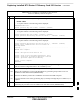
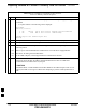

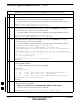


Table Of Contents
- Chapter 4: Acceptance Test Procedures
- Automated Acceptance Test Procedure
- Acceptance Tests - Test Set-up
- Abbreviated (All-inclusive) Acceptance Tests
- Individual Acceptance Tests
- TX Spectral Purity Transmit Mask Acceptance Test
- TX Waveform Quality (Rho) Acceptance Test
- TX Pilot Time Offset Acceptance Test
- TX Code Domain Power/Noise Floor Acceptance Test
- RX FER Acceptance Test
- Generating an ATP Report
- Updating Calibration Data Files
- Chapter 5: Prepare to Leave the Site
- Chapter 6: Troubleshooting
- Basic Troubleshooting: Overview
- Troubleshooting: Installation
- Cannot Log into Cell-Site
- Force LAN A Active (LMF Connection at I/O Panel LAN Connector)
- Force LAN A Active (LMF Connection at Service Shelf LAN Connector)
- Set the GLI IP Address
- Cannot Communicate with Power Meter
- Cannot Communicate with Communications System Analyzer
- Cannot Communicate with Signal Generator
- Troubleshooting: Download
- Troubleshooting: Calibration
- Basic Troubleshooting: RF Path Fault Isolation
- Troubleshooting: Transmit ATP
- Troubleshooting: Receive ATP
- Troubleshooting: CSM Checklist
- Troubleshooting: SCCP Backplane
- Troubleshooting: RFDS
- Module Front Panel LED Indicators and Connectors
- Troubleshooting: Span Control Link
- Appendix A: Data Sheets
- Appendix B: PN Offset/I & Q Offset Register Programming Information
- Appendix C: FRU Optimization / ATP Test Matrix
- Appendix D: BBX Gain Set Point vs. BTS Output
- Appendix E: CDMA Operating Frequency Programming Information
- Appendix F: Test Equipment Preparation
- Test Equipment Preparation
- Verifying and Setting GPIB Addresses
- Agilent E4406A Transmitter Tester GPIB Address
- Agilent E4432B Signal Generator GPIB Address
- Advantest R3267 Spectrum Analyzer GPIB Address
- Advantest R3562 Signal Generator GPIB Address
- Agilent 8935 Series E6380 (formerly HP 8935) Test Set GPIB Address
- Hewlett Packard HP 8921A and HP83236A/B GPIB Address
- Advantest R3465 Communications Test Set GPIB Address
- Motorola CyberTest GPIB Address
- HP 437 Power Meter GPIB Address
- Gigatronics 8541C Power Meter GPIB Address
- RS232 GPIB Interface Adapter
- Test Equipment Inter-Unit Connection, Testing, and Control
- Inter-Unit Connection, Testing, and Control Settings
- HP 8921A with PCS Interface Test Equipment Connections
- HP 8921A with PCS Interface System Connectivity Test
- Pretest Set-up for HP 8921A
- Pretest Set-up for Agilent 8935
- Advantest R3465 Connection
- R3465 GPIB Clock Set-up
- Pretest Set-up for Advantest R3465
- Agilent 8932/E4432B Test Equipment Interconnection
- Agilent E4406A/E4432B Test Equipment Interconnection
- Advantest R3267/R3562 Test Equipment Interconnection
- Equipment Calibration
- Manual Cable Calibration
- Appendix G: Downloading ROM Code
- Appendix H: In-Service Calibration
- Appendix I: Packet Backhaul Configuration
- BTS Router Initial Configuration
- Terminal Setup
- Downloading Minimum Canned BTS Router Configuration Files
- Verifying IOS Canned Version of the CF Memory Card
- Replacing Installed BTS Router CF Memory Card IOS Version
- Background
- Equipment and Software Required for Verification Methods
- Required Publications
- Method 1: Replacement of Installed Router CF Card IOS Data
- Method 2: Using a CF Memory Card Reader for Replacement of Installed IOS Version and Changing File Sequence ...
- Change CF Memory Card File Sequence to Place IOS File First on the Card
- Verify and Upgrade ROMMON Version
- Recovery from BTS Router Boot to ROMMON
- Entering or Changing Router FE Interface IP Address
- Preparation for Site Turn-over
- Index

Verify and Upgrade ROMMON Version – continued
FEB 2005 1X SC 4812T Lite BTS Optimization/ATP I-67
PRELIMINARY
Table I-13: Verify and Replace the Installed ROMMON Version using a TFTP Server
n Step Action
* IMPORTANT
This procedure does not cover all aspects of BTS Router Operation and programming.
Before performing this procedure, review BTS Router initialization, operation, and programming
information and procedures in MWR1941 Wireless Mobile Edge Router Software Configuration
Guide; part number 78–13983–01.
– Have this publication available for reference while performing this procedure.
1 This procedure assumes the LMF Computer and BTS Router are configured, connected, and
operating as they would be after performing the procedures in Table I-4, Table I-5, Table I-6, and
Steps 1 through 4 of Table I-7.
– If necessary, perform these procedures now.
2 Identify the installed ROMMON Version from the BTS Router Privileged EXEC Mode Prompt:
sh
ow version
– A response similar to the following will be displayed:
BTSRTR1#sh ver
Cisco Internetwork Operating System Software
IOS (tm) 1941 Software (MWR1941–I–M), Version 12.2(8)MC2b, EARLY DEPLOYMENT RE-
LEASE SOFTWARE (fc3)
TAC Support: http://www.cisco.com/tac
Copyright (c) 1986–2002 by cisco Systems, Inc.
Compiled Mon 05–Aug–02 11:07 by nmasa
Image text–base: 0x60008940, data–base: 0x60B54000
ROM: System Bootstrap, Version 12.2(20020113:235343) [sbose–wilma 109], DEVELOP-
MENT SOFTWARE
ROM: 1941 Software (MWR1941–I–M), Version 12.2(8)MC2b, EARLY DEPLOYMENT RELEASE
SOFTWARE (fc3)
Router uptime is 1 minute
System returned to ROM by power–on
System image file is ”slot0:mwr1941–i–mz.122–8.MC2b.bin”
cisco mwr1941 (R7000) processor (revision 0.1) with 121856K/18432K bytes of
memory.
Processor board ID JMX0611K5TS
R7000 CPU at 240Mhz, Implementation 39, Rev 3.3, 256KB L2 Cache
Bridging software.
X.25 software, Version 3.0.0.
Primary Rate ISDN software, Version 1.1.
Toaster processor tmc is running.
2 FastEthernet/IEEE 802.3 interface(s)
2 Serial network interface(s)
2 Channelized T1/PRI port(s)
DRAM configuration is 64 bits wide with parity disabled.
55K bytes of non–volatile configuration memory.
31360K bytes of ATA Slot0 CompactFlash (Read/Write)
Configuration register is 0x101
BTSRTR1#
table continued on next page
I