
User's Manual


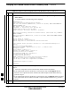

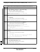

Table Of Contents
- Chapter 4: Acceptance Test Procedures
- Automated Acceptance Test Procedure
- Acceptance Tests - Test Set-up
- Abbreviated (All-inclusive) Acceptance Tests
- Individual Acceptance Tests
- TX Spectral Purity Transmit Mask Acceptance Test
- TX Waveform Quality (Rho) Acceptance Test
- TX Pilot Time Offset Acceptance Test
- TX Code Domain Power/Noise Floor Acceptance Test
- RX FER Acceptance Test
- Generating an ATP Report
- Updating Calibration Data Files
- Chapter 5: Prepare to Leave the Site
- Chapter 6: Troubleshooting
- Basic Troubleshooting: Overview
- Troubleshooting: Installation
- Cannot Log into Cell-Site
- Force LAN A Active (LMF Connection at I/O Panel LAN Connector)
- Force LAN A Active (LMF Connection at Service Shelf LAN Connector)
- Set the GLI IP Address
- Cannot Communicate with Power Meter
- Cannot Communicate with Communications System Analyzer
- Cannot Communicate with Signal Generator
- Troubleshooting: Download
- Troubleshooting: Calibration
- Basic Troubleshooting: RF Path Fault Isolation
- Troubleshooting: Transmit ATP
- Troubleshooting: Receive ATP
- Troubleshooting: CSM Checklist
- Troubleshooting: SCCP Backplane
- Troubleshooting: RFDS
- Module Front Panel LED Indicators and Connectors
- Troubleshooting: Span Control Link
- Appendix A: Data Sheets
- Appendix B: PN Offset/I & Q Offset Register Programming Information
- Appendix C: FRU Optimization / ATP Test Matrix
- Appendix D: BBX Gain Set Point vs. BTS Output
- Appendix E: CDMA Operating Frequency Programming Information
- Appendix F: Test Equipment Preparation
- Test Equipment Preparation
- Verifying and Setting GPIB Addresses
- Agilent E4406A Transmitter Tester GPIB Address
- Agilent E4432B Signal Generator GPIB Address
- Advantest R3267 Spectrum Analyzer GPIB Address
- Advantest R3562 Signal Generator GPIB Address
- Agilent 8935 Series E6380 (formerly HP 8935) Test Set GPIB Address
- Hewlett Packard HP 8921A and HP83236A/B GPIB Address
- Advantest R3465 Communications Test Set GPIB Address
- Motorola CyberTest GPIB Address
- HP 437 Power Meter GPIB Address
- Gigatronics 8541C Power Meter GPIB Address
- RS232 GPIB Interface Adapter
- Test Equipment Inter-Unit Connection, Testing, and Control
- Inter-Unit Connection, Testing, and Control Settings
- HP 8921A with PCS Interface Test Equipment Connections
- HP 8921A with PCS Interface System Connectivity Test
- Pretest Set-up for HP 8921A
- Pretest Set-up for Agilent 8935
- Advantest R3465 Connection
- R3465 GPIB Clock Set-up
- Pretest Set-up for Advantest R3465
- Agilent 8932/E4432B Test Equipment Interconnection
- Agilent E4406A/E4432B Test Equipment Interconnection
- Advantest R3267/R3562 Test Equipment Interconnection
- Equipment Calibration
- Manual Cable Calibration
- Appendix G: Downloading ROM Code
- Appendix H: In-Service Calibration
- Appendix I: Packet Backhaul Configuration
- BTS Router Initial Configuration
- Terminal Setup
- Downloading Minimum Canned BTS Router Configuration Files
- Verifying IOS Canned Version of the CF Memory Card
- Replacing Installed BTS Router CF Memory Card IOS Version
- Background
- Equipment and Software Required for Verification Methods
- Required Publications
- Method 1: Replacement of Installed Router CF Card IOS Data
- Method 2: Using a CF Memory Card Reader for Replacement of Installed IOS Version and Changing File Sequence ...
- Change CF Memory Card File Sequence to Place IOS File First on the Card
- Verify and Upgrade ROMMON Version
- Recovery from BTS Router Boot to ROMMON
- Entering or Changing Router FE Interface IP Address
- Preparation for Site Turn-over
- Index

Verifying IOS Canned Version of the CF Memory Card – continued
FEB 2005 1X SC 4812T Lite BTS Optimization/ATP I-23
PRELIMINARY
BTS Router Power–up and Initial Configuration for Ethernet
Communication
Perform the procedure in Table I-6 to apply power to the BTS Router
and set an Initial Configuration for Ethernet Communication.
S Ensure that the required version of the IOS is loaded on the CF
Memory Card.
S Ensure that the CF Memory Card is installed in the BTS Router.
Table I-6: BTS Router Power–up and Initial Ethernet Configuration Procedure
n Step Action
* IMPORTANT
This procedure does not cover all aspects of BTS Router Operation and programming.
Before performing this procedure, review BTS Router initialization, operation, and programming
information and procedures in MWR1941 Wireless Mobile Edge Router Software Configuration
Guide; part number 78–13983–01.
– Have this publication available for reference while performing this procedure.
1 Ensure that a CF Memory Card loaded with the Cisco IOS is installed in the BTS Router.
– Refer to the BTS Router Card and Module Replacement section of the 1X SC4812T Lite BTS
FRU manual (68P09262A60) for instructions to access the CF Memory Card Slot.
* IMPORTANT
In Step 2, do not touch the computer keyboard until the BTS Router completes the Boot Process.
The BTS Router buffers any keystrokes made during the Boot Process and interprets them as
commands to be executed immediately following completion of the Boot Process.
2 Apply power to the BTS Router and allow it to complete the Boot Process.
S If a message similar to the following, is displayed, press the Enter Key and proceed to Step 3.
Press RETURN to get started!
S If a message similar to the following, is displayed type no and press the Enter Key:
Basic management set–up configures only enough connectivity
for management of the system, extended set–up will ask you
to configure each interface on the system
Would you like to enter basic management set–up? [yes/no]:
A response similar to the following will be displayed:
Would you like to enter basic management set–up? [yes/no]: no
Cisco Internetwork Operating System Software
IOS (tm) 1941 Software (MWR1941–I–M), Version 12.2(20020127:101239
Copyright (c) 1986–2002 by cisco Systems, Inc.
Compiled Sun 27–Jan–02 06:08 by walrobin
Router>
table continued on next page
I