
User's Manual


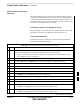


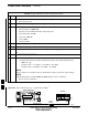
Table Of Contents
- Chapter 4: Acceptance Test Procedures
- Automated Acceptance Test Procedure
- Acceptance Tests - Test Set-up
- Abbreviated (All-inclusive) Acceptance Tests
- Individual Acceptance Tests
- TX Spectral Purity Transmit Mask Acceptance Test
- TX Waveform Quality (Rho) Acceptance Test
- TX Pilot Time Offset Acceptance Test
- TX Code Domain Power/Noise Floor Acceptance Test
- RX FER Acceptance Test
- Generating an ATP Report
- Updating Calibration Data Files
- Chapter 5: Prepare to Leave the Site
- Chapter 6: Troubleshooting
- Basic Troubleshooting: Overview
- Troubleshooting: Installation
- Cannot Log into Cell-Site
- Force LAN A Active (LMF Connection at I/O Panel LAN Connector)
- Force LAN A Active (LMF Connection at Service Shelf LAN Connector)
- Set the GLI IP Address
- Cannot Communicate with Power Meter
- Cannot Communicate with Communications System Analyzer
- Cannot Communicate with Signal Generator
- Troubleshooting: Download
- Troubleshooting: Calibration
- Basic Troubleshooting: RF Path Fault Isolation
- Troubleshooting: Transmit ATP
- Troubleshooting: Receive ATP
- Troubleshooting: CSM Checklist
- Troubleshooting: SCCP Backplane
- Troubleshooting: RFDS
- Module Front Panel LED Indicators and Connectors
- Troubleshooting: Span Control Link
- Appendix A: Data Sheets
- Appendix B: PN Offset/I & Q Offset Register Programming Information
- Appendix C: FRU Optimization / ATP Test Matrix
- Appendix D: BBX Gain Set Point vs. BTS Output
- Appendix E: CDMA Operating Frequency Programming Information
- Appendix F: Test Equipment Preparation
- Test Equipment Preparation
- Verifying and Setting GPIB Addresses
- Agilent E4406A Transmitter Tester GPIB Address
- Agilent E4432B Signal Generator GPIB Address
- Advantest R3267 Spectrum Analyzer GPIB Address
- Advantest R3562 Signal Generator GPIB Address
- Agilent 8935 Series E6380 (formerly HP 8935) Test Set GPIB Address
- Hewlett Packard HP 8921A and HP83236A/B GPIB Address
- Advantest R3465 Communications Test Set GPIB Address
- Motorola CyberTest GPIB Address
- HP 437 Power Meter GPIB Address
- Gigatronics 8541C Power Meter GPIB Address
- RS232 GPIB Interface Adapter
- Test Equipment Inter-Unit Connection, Testing, and Control
- Inter-Unit Connection, Testing, and Control Settings
- HP 8921A with PCS Interface Test Equipment Connections
- HP 8921A with PCS Interface System Connectivity Test
- Pretest Set-up for HP 8921A
- Pretest Set-up for Agilent 8935
- Advantest R3465 Connection
- R3465 GPIB Clock Set-up
- Pretest Set-up for Advantest R3465
- Agilent 8932/E4432B Test Equipment Interconnection
- Agilent E4406A/E4432B Test Equipment Interconnection
- Advantest R3267/R3562 Test Equipment Interconnection
- Equipment Calibration
- Manual Cable Calibration
- Appendix G: Downloading ROM Code
- Appendix H: In-Service Calibration
- Appendix I: Packet Backhaul Configuration
- BTS Router Initial Configuration
- Terminal Setup
- Downloading Minimum Canned BTS Router Configuration Files
- Verifying IOS Canned Version of the CF Memory Card
- Replacing Installed BTS Router CF Memory Card IOS Version
- Background
- Equipment and Software Required for Verification Methods
- Required Publications
- Method 1: Replacement of Installed Router CF Card IOS Data
- Method 2: Using a CF Memory Card Reader for Replacement of Installed IOS Version and Changing File Sequence ...
- Change CF Memory Card File Sequence to Place IOS File First on the Card
- Verify and Upgrade ROMMON Version
- Recovery from BTS Router Boot to ROMMON
- Entering or Changing Router FE Interface IP Address
- Preparation for Site Turn-over
- Index

Power Delta Calibration – continued
H-12 1X SC 4812T Lite BTS Optimization/ATP FEB 2005
PRELIMINARY
Table H-3: Agilent 8935 Power Delta Calibration Procedure
n ActionStep
7 Connect the short RF Cable between the Agilent 8935 Duplex Out Port and the RF–IN/OUT Port.
– Refer to Figure H-6.
8 Ensure that the Source Agilent 8935 Settings are the same as in Step 3.
9 Set the Agilent 8935 as follows:
– Measure Mode to CDMA Anl
– Frequency to the CDMA Calibration Target Frequency
– Input Attenuation to 0 dB
– Input Port to RF–IN
– Gain to Auto
– Anl Dir to Fwd
10 Turn on the Agilent 8935 Signal Output.
11 Set the Chn Pwr Cal to Calibrate and select to calibrate.
12 Measure and record the Channel Power Reading on the measuring Agilent 8935 as Result B.
B ________________________
13 Turn off the Agilent 8935 Signal Output and disconnect the equipment.
14 Calculate the Power Calibration Delta Value.
– The Delta Value is the Power Meter Measurement minus the Advantest Measurement.
Delta = A – B
Example: Delta = –0.70 dBm – (–1.25 dBm) = 0.55 dBm
Example: Delta = 0.26 dBm – 0.55 dBm = –0.29 dBm
NOTE
These examples are included to show the mathematics and do not represent actual readings.
NOTE
Add this Delta Value to the TX Cable Loss Value during In–Service Calibration.
– Refer to Step 4 in Table H-6.
Power
Sensor
Agilent Agilent 8935
Á
Á
Á
Á
Á
Á
Á
Á
Á
Á
Á
DUPLEX OUT
Short RF Cable
HP437B
SENSOR
FW00805
Figure H-5: Delta Calibration Set–up – Agilent 8935 to HP437
H