
User's Manual


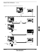

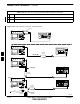
Table Of Contents
- Chapter 4: Acceptance Test Procedures
- Automated Acceptance Test Procedure
- Acceptance Tests - Test Set-up
- Abbreviated (All-inclusive) Acceptance Tests
- Individual Acceptance Tests
- TX Spectral Purity Transmit Mask Acceptance Test
- TX Waveform Quality (Rho) Acceptance Test
- TX Pilot Time Offset Acceptance Test
- TX Code Domain Power/Noise Floor Acceptance Test
- RX FER Acceptance Test
- Generating an ATP Report
- Updating Calibration Data Files
- Chapter 5: Prepare to Leave the Site
- Chapter 6: Troubleshooting
- Basic Troubleshooting: Overview
- Troubleshooting: Installation
- Cannot Log into Cell-Site
- Force LAN A Active (LMF Connection at I/O Panel LAN Connector)
- Force LAN A Active (LMF Connection at Service Shelf LAN Connector)
- Set the GLI IP Address
- Cannot Communicate with Power Meter
- Cannot Communicate with Communications System Analyzer
- Cannot Communicate with Signal Generator
- Troubleshooting: Download
- Troubleshooting: Calibration
- Basic Troubleshooting: RF Path Fault Isolation
- Troubleshooting: Transmit ATP
- Troubleshooting: Receive ATP
- Troubleshooting: CSM Checklist
- Troubleshooting: SCCP Backplane
- Troubleshooting: RFDS
- Module Front Panel LED Indicators and Connectors
- Troubleshooting: Span Control Link
- Appendix A: Data Sheets
- Appendix B: PN Offset/I & Q Offset Register Programming Information
- Appendix C: FRU Optimization / ATP Test Matrix
- Appendix D: BBX Gain Set Point vs. BTS Output
- Appendix E: CDMA Operating Frequency Programming Information
- Appendix F: Test Equipment Preparation
- Test Equipment Preparation
- Verifying and Setting GPIB Addresses
- Agilent E4406A Transmitter Tester GPIB Address
- Agilent E4432B Signal Generator GPIB Address
- Advantest R3267 Spectrum Analyzer GPIB Address
- Advantest R3562 Signal Generator GPIB Address
- Agilent 8935 Series E6380 (formerly HP 8935) Test Set GPIB Address
- Hewlett Packard HP 8921A and HP83236A/B GPIB Address
- Advantest R3465 Communications Test Set GPIB Address
- Motorola CyberTest GPIB Address
- HP 437 Power Meter GPIB Address
- Gigatronics 8541C Power Meter GPIB Address
- RS232 GPIB Interface Adapter
- Test Equipment Inter-Unit Connection, Testing, and Control
- Inter-Unit Connection, Testing, and Control Settings
- HP 8921A with PCS Interface Test Equipment Connections
- HP 8921A with PCS Interface System Connectivity Test
- Pretest Set-up for HP 8921A
- Pretest Set-up for Agilent 8935
- Advantest R3465 Connection
- R3465 GPIB Clock Set-up
- Pretest Set-up for Advantest R3465
- Agilent 8932/E4432B Test Equipment Interconnection
- Agilent E4406A/E4432B Test Equipment Interconnection
- Advantest R3267/R3562 Test Equipment Interconnection
- Equipment Calibration
- Manual Cable Calibration
- Appendix G: Downloading ROM Code
- Appendix H: In-Service Calibration
- Appendix I: Packet Backhaul Configuration
- BTS Router Initial Configuration
- Terminal Setup
- Downloading Minimum Canned BTS Router Configuration Files
- Verifying IOS Canned Version of the CF Memory Card
- Replacing Installed BTS Router CF Memory Card IOS Version
- Background
- Equipment and Software Required for Verification Methods
- Required Publications
- Method 1: Replacement of Installed Router CF Card IOS Data
- Method 2: Using a CF Memory Card Reader for Replacement of Installed IOS Version and Changing File Sequence ...
- Change CF Memory Card File Sequence to Place IOS File First on the Card
- Verify and Upgrade ROMMON Version
- Recovery from BTS Router Boot to ROMMON
- Entering or Changing Router FE Interface IP Address
- Preparation for Site Turn-over
- Index

Manual Cable Calibration – continued
F-40 1X SC 4812T Lite BTS Optimization/ATP FEB 2005
PRELIMINARY
Calibrating the Test Cable
Set–up with the Advantest
R3465
Ensure that the GPIB Interface is OFF for the duration of
this procedure.
IMPORTANT
*
Advantest R3465 Manual Test Set–up and Calibration must be
performed on both the TX and RX Frequencies.
Table F-24: Test Cable Set–up (using Advantest R3465) Calibration Procedure
n Step Action
* IMPORTANT
This procedure can only be performed after Test Equipment has been allowed to warm–up and
stabilize for a minimum of 60 minutes.
1 Press the SHIFT and the PRESET Keys located below the display.
2 Press the ADVANCE Key in the MEASUREMENT area of the Control Panel.
3 Select the CDMA Sig CRT Menu Key.
4 Select the Set–up CRT Menu Key.
5 Use the Vernier Knob and the Cursor Keys to set the following parameters.
Generator Mode: SIGNAL
Link: FORWARD
Level Unit: dBm
CalCorrection: ON
Level Offset: OFF
NOTE
Fields not listed remain at default values.
6 Select the Return CRT Menu Key.
7 Press FREQ Key in the ENTRY Area.
8 Set the Frequency to the desired value by using the Keypad Entry Keys.
9 Verify that the Mod CRT Menu Key highlighting is OFF.
S If it is highlighting OFF, proceed to Step 10.
S If it is not highlighting OFF:
– Press the Mod Key to toggle it OFF.
– Proceed to Step 10.
table continued on next page
F