
User's Manual
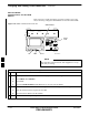
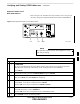
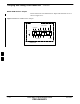

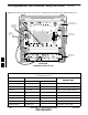


Table Of Contents
- Chapter 4: Acceptance Test Procedures
- Automated Acceptance Test Procedure
- Acceptance Tests - Test Set-up
- Abbreviated (All-inclusive) Acceptance Tests
- Individual Acceptance Tests
- TX Spectral Purity Transmit Mask Acceptance Test
- TX Waveform Quality (Rho) Acceptance Test
- TX Pilot Time Offset Acceptance Test
- TX Code Domain Power/Noise Floor Acceptance Test
- RX FER Acceptance Test
- Generating an ATP Report
- Updating Calibration Data Files
- Chapter 5: Prepare to Leave the Site
- Chapter 6: Troubleshooting
- Basic Troubleshooting: Overview
- Troubleshooting: Installation
- Cannot Log into Cell-Site
- Force LAN A Active (LMF Connection at I/O Panel LAN Connector)
- Force LAN A Active (LMF Connection at Service Shelf LAN Connector)
- Set the GLI IP Address
- Cannot Communicate with Power Meter
- Cannot Communicate with Communications System Analyzer
- Cannot Communicate with Signal Generator
- Troubleshooting: Download
- Troubleshooting: Calibration
- Basic Troubleshooting: RF Path Fault Isolation
- Troubleshooting: Transmit ATP
- Troubleshooting: Receive ATP
- Troubleshooting: CSM Checklist
- Troubleshooting: SCCP Backplane
- Troubleshooting: RFDS
- Module Front Panel LED Indicators and Connectors
- Troubleshooting: Span Control Link
- Appendix A: Data Sheets
- Appendix B: PN Offset/I & Q Offset Register Programming Information
- Appendix C: FRU Optimization / ATP Test Matrix
- Appendix D: BBX Gain Set Point vs. BTS Output
- Appendix E: CDMA Operating Frequency Programming Information
- Appendix F: Test Equipment Preparation
- Test Equipment Preparation
- Verifying and Setting GPIB Addresses
- Agilent E4406A Transmitter Tester GPIB Address
- Agilent E4432B Signal Generator GPIB Address
- Advantest R3267 Spectrum Analyzer GPIB Address
- Advantest R3562 Signal Generator GPIB Address
- Agilent 8935 Series E6380 (formerly HP 8935) Test Set GPIB Address
- Hewlett Packard HP 8921A and HP83236A/B GPIB Address
- Advantest R3465 Communications Test Set GPIB Address
- Motorola CyberTest GPIB Address
- HP 437 Power Meter GPIB Address
- Gigatronics 8541C Power Meter GPIB Address
- RS232 GPIB Interface Adapter
- Test Equipment Inter-Unit Connection, Testing, and Control
- Inter-Unit Connection, Testing, and Control Settings
- HP 8921A with PCS Interface Test Equipment Connections
- HP 8921A with PCS Interface System Connectivity Test
- Pretest Set-up for HP 8921A
- Pretest Set-up for Agilent 8935
- Advantest R3465 Connection
- R3465 GPIB Clock Set-up
- Pretest Set-up for Advantest R3465
- Agilent 8932/E4432B Test Equipment Interconnection
- Agilent E4406A/E4432B Test Equipment Interconnection
- Advantest R3267/R3562 Test Equipment Interconnection
- Equipment Calibration
- Manual Cable Calibration
- Appendix G: Downloading ROM Code
- Appendix H: In-Service Calibration
- Appendix I: Packet Backhaul Configuration
- BTS Router Initial Configuration
- Terminal Setup
- Downloading Minimum Canned BTS Router Configuration Files
- Verifying IOS Canned Version of the CF Memory Card
- Replacing Installed BTS Router CF Memory Card IOS Version
- Background
- Equipment and Software Required for Verification Methods
- Required Publications
- Method 1: Replacement of Installed Router CF Card IOS Data
- Method 2: Using a CF Memory Card Reader for Replacement of Installed IOS Version and Changing File Sequence ...
- Change CF Memory Card File Sequence to Place IOS File First on the Card
- Verify and Upgrade ROMMON Version
- Recovery from BTS Router Boot to ROMMON
- Entering or Changing Router FE Interface IP Address
- Preparation for Site Turn-over
- Index

Test Equipment Inter–Unit Connection, Testing, and Control
FEB 2005 1X SC 4812T Lite BTS Optimization/ATP F-19
PRELIMINARY
Inter–Unit Connection, Testing,
and Control Settings
The following illustrations, tables, and procedures provide the
information necessary to prepare various items of CDMA Test
Equipment supported by the LMF for BTS Calibration and/or
Acceptance Testing.
HP 8921A with PCS Interface
Test Equipment Connections
The following diagram depicts the rear panels of the HP 8921A Test
Equipment as configured to perform automatic tests. All Test Equipment
is controlled by the LMF via an IEEE–488/GPIB Bus.
The LMF expects each piece of Test Equipment to have a factory-set
GPIB Address (refer to Table F-8 and Figure F-8). If there is a
communications problem between the LMF and any piece of Test
Equipment, verify that the GPIB Addresses have been set correctly and
that the GPIB Cables are firmly connected to the Test Equipment.
Figure F-13 shows the connections when not using an external 10 MHz
Rubidium Reference.
Table F-13: HP 8921A/600 Communications Test Set Rear Panel Connections
without Rubidium Reference
From Test Set: To Interface:
Connector Type
8921A 83203B CDMA 83236A PCS
C
onnector
T
ype
CW RF OUT CW RF IN SMC–Female – SMC–Female
114.3 MHZ IF OUT 114.3 MHZ IF IN SMC–Female – SMC–Female
IQ RF IN IQ RF OUT SMC–Female – SMC–Female
DET OUT AUX DSP IN SMC–Female – SMC–Female
CONTROL I/O CONTROL I/O 45–pin Custom BUS
10 MHZ OUT SYNTH REF IN BNC–Male – BNC–Male
HPIB INTERFACE HPIB INTERFACE HPIB Cable
10 MHZ OUT REF IN BNC–Male – BNC–Male
F