
User's Manual

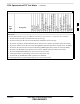

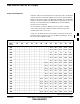
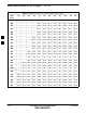

Table Of Contents
- Chapter 4: Acceptance Test Procedures
- Automated Acceptance Test Procedure
- Acceptance Tests - Test Set-up
- Abbreviated (All-inclusive) Acceptance Tests
- Individual Acceptance Tests
- TX Spectral Purity Transmit Mask Acceptance Test
- TX Waveform Quality (Rho) Acceptance Test
- TX Pilot Time Offset Acceptance Test
- TX Code Domain Power/Noise Floor Acceptance Test
- RX FER Acceptance Test
- Generating an ATP Report
- Updating Calibration Data Files
- Chapter 5: Prepare to Leave the Site
- Chapter 6: Troubleshooting
- Basic Troubleshooting: Overview
- Troubleshooting: Installation
- Cannot Log into Cell-Site
- Force LAN A Active (LMF Connection at I/O Panel LAN Connector)
- Force LAN A Active (LMF Connection at Service Shelf LAN Connector)
- Set the GLI IP Address
- Cannot Communicate with Power Meter
- Cannot Communicate with Communications System Analyzer
- Cannot Communicate with Signal Generator
- Troubleshooting: Download
- Troubleshooting: Calibration
- Basic Troubleshooting: RF Path Fault Isolation
- Troubleshooting: Transmit ATP
- Troubleshooting: Receive ATP
- Troubleshooting: CSM Checklist
- Troubleshooting: SCCP Backplane
- Troubleshooting: RFDS
- Module Front Panel LED Indicators and Connectors
- Troubleshooting: Span Control Link
- Appendix A: Data Sheets
- Appendix B: PN Offset/I & Q Offset Register Programming Information
- Appendix C: FRU Optimization / ATP Test Matrix
- Appendix D: BBX Gain Set Point vs. BTS Output
- Appendix E: CDMA Operating Frequency Programming Information
- Appendix F: Test Equipment Preparation
- Test Equipment Preparation
- Verifying and Setting GPIB Addresses
- Agilent E4406A Transmitter Tester GPIB Address
- Agilent E4432B Signal Generator GPIB Address
- Advantest R3267 Spectrum Analyzer GPIB Address
- Advantest R3562 Signal Generator GPIB Address
- Agilent 8935 Series E6380 (formerly HP 8935) Test Set GPIB Address
- Hewlett Packard HP 8921A and HP83236A/B GPIB Address
- Advantest R3465 Communications Test Set GPIB Address
- Motorola CyberTest GPIB Address
- HP 437 Power Meter GPIB Address
- Gigatronics 8541C Power Meter GPIB Address
- RS232 GPIB Interface Adapter
- Test Equipment Inter-Unit Connection, Testing, and Control
- Inter-Unit Connection, Testing, and Control Settings
- HP 8921A with PCS Interface Test Equipment Connections
- HP 8921A with PCS Interface System Connectivity Test
- Pretest Set-up for HP 8921A
- Pretest Set-up for Agilent 8935
- Advantest R3465 Connection
- R3465 GPIB Clock Set-up
- Pretest Set-up for Advantest R3465
- Agilent 8932/E4432B Test Equipment Interconnection
- Agilent E4406A/E4432B Test Equipment Interconnection
- Advantest R3267/R3562 Test Equipment Interconnection
- Equipment Calibration
- Manual Cable Calibration
- Appendix G: Downloading ROM Code
- Appendix H: In-Service Calibration
- Appendix I: Packet Backhaul Configuration
- BTS Router Initial Configuration
- Terminal Setup
- Downloading Minimum Canned BTS Router Configuration Files
- Verifying IOS Canned Version of the CF Memory Card
- Replacing Installed BTS Router CF Memory Card IOS Version
- Background
- Equipment and Software Required for Verification Methods
- Required Publications
- Method 1: Replacement of Installed Router CF Card IOS Data
- Method 2: Using a CF Memory Card Reader for Replacement of Installed IOS Version and Changing File Sequence ...
- Change CF Memory Card File Sequence to Place IOS File First on the Card
- Verify and Upgrade ROMMON Version
- Recovery from BTS Router Boot to ROMMON
- Entering or Changing Router FE Interface IP Address
- Preparation for Site Turn-over
- Index

BBX Gain Set Point vs. BTS Output
FEB 2005 1X SC 4812T Lite BTS Optimization/ATP D-1
PRELIMINARY
Usage and Background
Table D-1 outlines the relationship between the total of all Code Domain
Channel Element Gain Settings (digital root sum of the squares) and the
BBX Gain Set Point between 33.0 dBm and 44.0 dBm. The resultant RF
Output (as measured in dBm at the BTS Antenna Connector) is shown in
the table. The table assumes that the BBX Bay Level Offset (BLO)
Values have been calculated.
As an illustration, consider a BBX keyed–up to produce a CDMA
Carrier with only the Pilot Channel (no MCC Cards Forward Link
enabled). Pilot Gain is set to 262.
In this case, the BBX Gain Set Point is shown to correlate exactly to the
actual RF Output anywhere in the 33 to 44 dBm Output Range. This is
the level used to calibrate the BTS.
Table D-1: BBX Gain Set Point vs. Actual BTS Output (in dBm)
dBm’
Gainb
44 43 42 41 40 39 38 37 36 35 34 33
541 – – – – – – – 43.3 42.3 41.3 40.3 39.3
533 – – – – – – – 43.2 42.2 41.2 40.2 39.2
525 – – – – – – – 43 42 41 40 39
517 – – – – – – – 42.9 41.9 40.9 39.9 38.9
509 – – – – – – – 42.8 41.8 40.8 39.8 38.8
501 – – – – – – – 42.6 41.6 40.6 39.6 38.6
493 – – – – – – 43.5 42.5 41.5 40.5 39.5 38.5
485 – – – – – – 43.4 42.4 41.4 40.4 39.4 38.4
477 – – – – – – 43.2 42.2 41.2 40.2 39.2 38.2
469 – – – – – – 43.1 42.1 41.1 40.1 39.1 38.1
461 – – – – – – 42.9 41.9 40.9 39.9 38.9 37.9
453 – – – – – – 42.8 41.8 40.8 39.8 38.8 37.8
445 – – – – – 43.6 42.6 41.6 40.6 39.6 38.6 37.6
437 – – – – – 43.4 42.4 41.4 40.4 39.4 38.4 37.4
429 – – – – – 43.3 42.3 41.3 40.3 39.3 38.3 37.3
421 – – – – – 43.1 42.1 41.1 40.1 39.1 38.1 37.1
413 – – – – – 43 42 41 40 39 38 37
405 – – – – – 42.8 41.8 40.8 39.8 38.8 37.8 36.8
table continued next page
D