
User's Manual

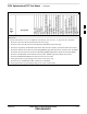


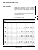
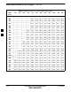

Table Of Contents
- Chapter 4: Acceptance Test Procedures
- Automated Acceptance Test Procedure
- Acceptance Tests - Test Set-up
- Abbreviated (All-inclusive) Acceptance Tests
- Individual Acceptance Tests
- TX Spectral Purity Transmit Mask Acceptance Test
- TX Waveform Quality (Rho) Acceptance Test
- TX Pilot Time Offset Acceptance Test
- TX Code Domain Power/Noise Floor Acceptance Test
- RX FER Acceptance Test
- Generating an ATP Report
- Updating Calibration Data Files
- Chapter 5: Prepare to Leave the Site
- Chapter 6: Troubleshooting
- Basic Troubleshooting: Overview
- Troubleshooting: Installation
- Cannot Log into Cell-Site
- Force LAN A Active (LMF Connection at I/O Panel LAN Connector)
- Force LAN A Active (LMF Connection at Service Shelf LAN Connector)
- Set the GLI IP Address
- Cannot Communicate with Power Meter
- Cannot Communicate with Communications System Analyzer
- Cannot Communicate with Signal Generator
- Troubleshooting: Download
- Troubleshooting: Calibration
- Basic Troubleshooting: RF Path Fault Isolation
- Troubleshooting: Transmit ATP
- Troubleshooting: Receive ATP
- Troubleshooting: CSM Checklist
- Troubleshooting: SCCP Backplane
- Troubleshooting: RFDS
- Module Front Panel LED Indicators and Connectors
- Troubleshooting: Span Control Link
- Appendix A: Data Sheets
- Appendix B: PN Offset/I & Q Offset Register Programming Information
- Appendix C: FRU Optimization / ATP Test Matrix
- Appendix D: BBX Gain Set Point vs. BTS Output
- Appendix E: CDMA Operating Frequency Programming Information
- Appendix F: Test Equipment Preparation
- Test Equipment Preparation
- Verifying and Setting GPIB Addresses
- Agilent E4406A Transmitter Tester GPIB Address
- Agilent E4432B Signal Generator GPIB Address
- Advantest R3267 Spectrum Analyzer GPIB Address
- Advantest R3562 Signal Generator GPIB Address
- Agilent 8935 Series E6380 (formerly HP 8935) Test Set GPIB Address
- Hewlett Packard HP 8921A and HP83236A/B GPIB Address
- Advantest R3465 Communications Test Set GPIB Address
- Motorola CyberTest GPIB Address
- HP 437 Power Meter GPIB Address
- Gigatronics 8541C Power Meter GPIB Address
- RS232 GPIB Interface Adapter
- Test Equipment Inter-Unit Connection, Testing, and Control
- Inter-Unit Connection, Testing, and Control Settings
- HP 8921A with PCS Interface Test Equipment Connections
- HP 8921A with PCS Interface System Connectivity Test
- Pretest Set-up for HP 8921A
- Pretest Set-up for Agilent 8935
- Advantest R3465 Connection
- R3465 GPIB Clock Set-up
- Pretest Set-up for Advantest R3465
- Agilent 8932/E4432B Test Equipment Interconnection
- Agilent E4406A/E4432B Test Equipment Interconnection
- Advantest R3267/R3562 Test Equipment Interconnection
- Equipment Calibration
- Manual Cable Calibration
- Appendix G: Downloading ROM Code
- Appendix H: In-Service Calibration
- Appendix I: Packet Backhaul Configuration
- BTS Router Initial Configuration
- Terminal Setup
- Downloading Minimum Canned BTS Router Configuration Files
- Verifying IOS Canned Version of the CF Memory Card
- Replacing Installed BTS Router CF Memory Card IOS Version
- Background
- Equipment and Software Required for Verification Methods
- Required Publications
- Method 1: Replacement of Installed Router CF Card IOS Data
- Method 2: Using a CF Memory Card Reader for Replacement of Installed IOS Version and Changing File Sequence ...
- Change CF Memory Card File Sequence to Place IOS File First on the Card
- Verify and Upgrade ROMMON Version
- Recovery from BTS Router Boot to ROMMON
- Entering or Changing Router FE Interface IP Address
- Preparation for Site Turn-over
- Index

FRU Optimization/ATP Test Matrix
FEB 2005 1X SC 4812T Lite BTS Optimization/ATP C-1
PRELIMINARY
Usage and Background
Periodic maintenance of a site may also mandate Re–Optimization of
specific portions of the site. An outline of some basic guidelines is
included in the following tables.
Re–Optimization Actions listed for any assembly detailed
in the tables below must be performed anytime an RF
Cable associated with it is replaced.
NOTE
Detailed Optimization/ATP Test
Matrix
Table C-1 outlines in more detail the tests that would need to be
performed if one of the BTS Components were to fail and be replaced. It
is also assumes that all modules are placed OOS–ROM via the LMF
until Full Redundancy of all applicable modules is implemented.
The following guidelines should also be noted when using this table:
Not every procedure required to bring the site back in
service is indicated in Table C-1. It is meant to be used as
a guideline ONLY.
The table assumes that the user is familiar enough with
the BTS Optimization/Acceptance Test Procedure to
understand which Test Equipment Set–ups, Calibrations,
and BTS Site preparation will be required before
performing the table number procedures referenced.
NOTE
Passive BTS components (such as the Bandpass Filters and 2:1
Combiners) only require a TX Calibration Audit to be performed in lieu
of a Full Path Calibration.
S If the TX Path Calibration Audit fails, the entire RF Path Calibration
will need to be repeated.
S If the RF Path Calibration fails, further troubleshooting is warranted.
If any significant change in signal level results from any
component being replaced in the RX or TX Signal Flow
Paths, it would be identified by re–running the RX and TX
Calibration Audit Command.
NOTE
When the CIO is replaced, the SCCP Cage remains powered up. The
BBX Cards may need to be removed, then re–installed into their original
slots, and re–downloaded (Code and BLO Data). RX and TX Calibration
Audits should then be performed on the affected Carrier Sectors.
C