
User's Manual
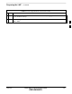
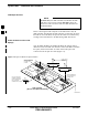
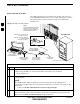
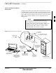
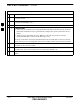
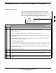
Table Of Contents
- Chapter 1: Introduction
- Chapter 2: Preparatory Tasks
- Chapter 3: Optimization/Calibration
- Introduction to Optimization and Calibration
- Preparing the LMF
- Overview of Packet BTS Files
- LMF Features and Installation Requirements
- LMF File Structure Overview
- LMF Home Directory
- NECF Filename Conventions and Directory Location
- LMF Installation and Update Procedures
- Copy BTS and CBSC CDF (or NECF) Files to the LMF Computer
- Creating a Named HyperTerminal Connection for MMI Communication
- Span Lines - Interface and Isolation
- LMF to BTS Connection
- Switching the Active LAN - LMF I/O Panel 10Base-2 LAN Connection

Span Lines – Interface and Isolation
3-16 1X SC 4812T Lite BTS Optimization/ATP FEB 2005
PRELIMINARY
T1/E1 Span Interface
At active sites, the OMC–R/CBSC must disable the BTS
and place it out of service (OOS). DO NOT remove the
Span Line Cable Connectors until the OMC–R/CBSC has
disabled the BTS.
NOTE
Before connecting the LMF Computer to the BTS Frame LAN, the
OMC–R/CBSC must disable the BTS and place it OOS. This will allow
the LMF to control the BTS, and prevent the CBSC from inadvertently
sending Control Information to the BTS during LMF–based Tests.
Isolate the BTS from the T1/E1
Span(s)
Once the OMC–R/CBSC has disabled the BTS, the Span(s) must be
disabled to ensure the LMF will maintain control of the BTS. To disable
the Spans, disconnect the BTS–to–CBSC Transcoder Span Cable
Connectors from the Span I/O Cards (Figure 3-2).
50–PIN TELCO
CONNECTORS
REMOVED
SPAN B CONNECTOR
(TELCO) INTERFACE
TO SPAN LINES
(IF USED
SPAN A CONNECTOR
(TELCO) INTERFACE
TO SPAN LINES
TOP of Frame
(Site I/O and Span I/O Boards)
RS–232 9–PIN SUB D
CONNECTOR SERIAL
PORT FOR EXTERNAL
DIAL UP MODEM
CONNECTION (IF USED)
FW00299 REF
Figure 3-2: Span I/O Board T1 Span Isolation
3