
User's Manual
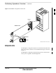
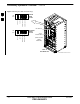
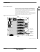
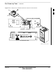
Table Of Contents
- Chapter 1: Introduction
- Chapter 2: Preparatory Tasks
- Chapter 3: Optimization/Calibration
- Introduction to Optimization and Calibration
- Preparing the LMF
- Overview of Packet BTS Files
- LMF Features and Installation Requirements
- LMF File Structure Overview
- LMF Home Directory
- NECF Filename Conventions and Directory Location
- LMF Installation and Update Procedures
- Copy BTS and CBSC CDF (or NECF) Files to the LMF Computer
- Creating a Named HyperTerminal Connection for MMI Communication
- Span Lines - Interface and Isolation
- LMF to BTS Connection
- Switching the Active LAN - LMF I/O Panel 10Base-2 LAN Connection

Initial Power–up Tests and Procedures
2-10 1X SC 4812T Lite BTS Optimization/ATP FEB 2005
PRELIMINARY
Power-up Procedures
Potentially lethal voltage and current levels are routed to
the BTS Equipment.
This test must be performed with a second person present
who will be acting in a safety role.
Remove all rings, jewelry, and wrist watches prior to
beginning this test.
WARNING
Input Power
In the tests to follow, power will first be verified at the input to each
BTS Frame. After power is verified, cards and modules within the frame
itself will be powered up and verified one at a time.
Before applying any power, verify that the correct Power Feed and
Return Cables are connected between the Power Supply Module Circuit
Breakers and the Power Connectors at the top of each BTS Frame.
Verify correct cable position referring to Figure 2-4 on Page 2-9.
Always wear a Conductive, High Impedance Wrist Strap
while handling any circuit card/module to prevent damage
by Electrostatic Discharge (ESD).
Extreme care should be taken during the removal and
installation of any card/module.
After removal, the card/module should be placed on a
conductive surface or back into the anti–static bag in
which it was shipped.
CAUTION
For Positive Power Applications (+27V):
– The Positive Power Cable is red.
– The Negative Power Cable is black.
For Negative Power Applications (–48V):
– The Negative Power Cable is red or blue.
– The Positive Power Cable (ground) is black.
NOTE
2