
User's Manual
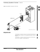
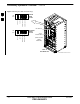
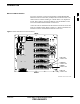
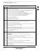
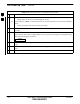
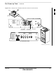
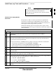
Table Of Contents
- Chapter 1: Introduction
- Chapter 2: Preparatory Tasks
- Chapter 3: Optimization/Calibration
- Introduction to Optimization and Calibration
- Preparing the LMF
- Overview of Packet BTS Files
- LMF Features and Installation Requirements
- LMF File Structure Overview
- LMF Home Directory
- NECF Filename Conventions and Directory Location
- LMF Installation and Update Procedures
- Copy BTS and CBSC CDF (or NECF) Files to the LMF Computer
- Creating a Named HyperTerminal Connection for MMI Communication
- Span Lines - Interface and Isolation
- LMF to BTS Connection
- Switching the Active LAN - LMF I/O Panel 10Base-2 LAN Connection

Pre–Power–up Tests – continued
2-8 1X SC 4812T Lite BTS Optimization/ATP FEB 2005
PRELIMINARY
Table 2-2: DC and AC Power Pre–test (BTS Frame) Procedure
n ActionStep
4d Access the L2/N terminal on the AC Filter or probe the L2/N socket in the PSM Slot.
– Lightly probe the socket to avoid damaging the socket.
4e If the reading is < 500 Ω, an electrical short may be present somewhere in the AC Filter and PSM
Shelf.
– Isolate the problem and correct it before proceeding.
5 Insert and lock the DC/DC Converter Modules for the SCCP Cage into their associated slots one
at a time.
! CAUTION
Verify that the correct Power Supply Modules are be ing used by checking the Locking/Retracting
Tabs. They should appear as follows.
STPN4009B
PWR C–CCP 4812 +27V
6 Insert and lock all remaining cards, boards, and modules into their assigned slots in the SCCP
Cage.
7 In the –48V and AC BTS Frames, insert the Power Supply Modules one at a time in their assigned
slots.
8 Seat all CLPA and associated CLPA Fan Modules into their slots in the shelves one at a time.
2