
User's Manual
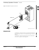
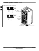
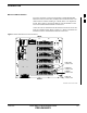
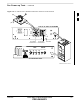
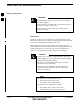
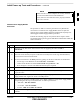
Table Of Contents
- Chapter 1: Introduction
- Chapter 2: Preparatory Tasks
- Chapter 3: Optimization/Calibration
- Introduction to Optimization and Calibration
- Preparing the LMF
- Overview of Packet BTS Files
- LMF Features and Installation Requirements
- LMF File Structure Overview
- LMF Home Directory
- NECF Filename Conventions and Directory Location
- LMF Installation and Update Procedures
- Copy BTS and CBSC CDF (or NECF) Files to the LMF Computer
- Creating a Named HyperTerminal Connection for MMI Communication
- Span Lines - Interface and Isolation
- LMF to BTS Connection
- Switching the Active LAN - LMF I/O Panel 10Base-2 LAN Connection

Preliminary Operations: Overview – continued
FEB 2005 1X SC 4812T Lite BTS Optimization/ATP 2-3
PRELIMINARY
ti-CDMA-WP-00228-v01-ildoc-ftw REF
Switch Card
1234
ON
BTS
MF
3–Sector
6–Sector
J1
J2
J3
J4
J5
SHIELDS
Configuration
Switch
Figure 2-1: 800 MHz Configuration Switch Card
Setting Frame SCCP
Configuration Switch
The Backplane Configuration Switch is located behind the BTS Frame
Rear Access Panel. It must be set for the BTS Frame Type as shown in
Figure 2-2.
The Backplane Configuration Switch Setting must be verified and set
before power is applied to the BTS Equipment.
2