
User's Manual
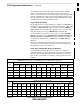
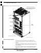
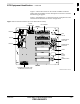
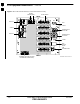
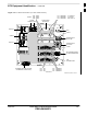
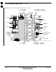
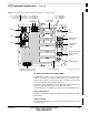
Table Of Contents
- Chapter 1: Introduction
- Chapter 2: Preparatory Tasks
- Chapter 3: Optimization/Calibration
- Introduction to Optimization and Calibration
- Preparing the LMF
- Overview of Packet BTS Files
- LMF Features and Installation Requirements
- LMF File Structure Overview
- LMF Home Directory
- NECF Filename Conventions and Directory Location
- LMF Installation and Update Procedures
- Copy BTS and CBSC CDF (or NECF) Files to the LMF Computer
- Creating a Named HyperTerminal Connection for MMI Communication
- Span Lines - Interface and Isolation
- LMF to BTS Connection
- Switching the Active LAN - LMF I/O Panel 10Base-2 LAN Connection

BTS Equipment Identification – continued
FEB 2005 1X SC 4812T Lite BTS Optimization/ATP 1-23
PRELIMINARY
ÂÂÂÂÂÂÂÂÂÂÂÂÂÂÂÂ
ÂÂÂÂÂÂÂÂÂÂÂÂÂÂÂÂ
ÂÂÂÂÂÂÂÂÂÂÂÂÂÂÂÂ
ÂÂÂÂÂÂÂÂÂÂÂÂÂÂÂÂ
ÂÂÂÂÂÂÂÂÂÂÂÂÂÂÂÂ
ÂÂÂÂÂÂÂÂÂÂÂÂÂÂÂÂ
ÂÂÂÂÂÂÂÂÂÂÂÂÂÂÂÂ
ÂÂÂÂÂÂÂÂÂÂÂÂÂÂÂÂ
ÂÂÂÂÂÂÂÂÂÂÂÂÂÂÂÂ
ÂÂÂÂÂÂÂÂÂÂÂÂÂÂÂÂ
ÂÂÂÂÂÂÂÂÂÂÂÂÂÂÂÂ
ÂÂÂÂÂÂÂÂÂÂÂÂÂÂÂÂ
ÂÂÂÂÂÂÂÂÂÂÂÂÂÂÂÂ
ÂÂÂÂÂÂÂÂÂÂÂÂÂÂÂÂ
ÂÂÂÂÂÂÂÂÂÂÂÂÂÂÂÂ
ÂÂÂÂÂÂÂÂÂÂÂÂÂÂÂÂ
ÂÂÂÂÂÂÂÂÂÂÂÂÂÂÂÂ
FRONT
SITE I/O
LAN
CONNECTIONS
GPS IN
HSO
POWER INPUT/
DC FILTER
ETHERNET ROUTER (IF USED;
OTHERWISE, FILLER PLATE)
REAR
SPAN I/O
ti-CDMA-WP-00326-v01-ildoc-ftw
ALARM
CONNECTORS
POWER INPUT/
AC FILTER
SPAN I/O
VTRIM
FILTER CABLE
BULKHEAD
FILLER PLATES (3)
TX1 – CARRIER 3
TX2 – CARRIER 3
TX3 – CARRIER 3
TX1 – CARRIER 4
TX2 – CARRIER 4
TX3 – CARRIER 4
To Combiners
(to combine
with Carrier 2)
Ports are not used
on 3 Carrier
Configuration
RF EXPANSION PORT
FROM STARTER
FRAME
Figure 1-7: I/O Interconnect Panel (Expansion Frame – 3 and 4 Carrier)
DC Power Distribution Assembly (PDA)
The BTS Frame requires +27V, provided by direct input (+27V Version),
–48V to +27V Power Converters (–48V Version), or AC Rectifiers and
External Battery Back–up (AC Version). The +27V Power is then routed
to the Circuit Breaker Panel. Refer to Figure 1-2.
The Breaker Panel distributes DC Power and System DC Bus Protection
from the Loads with Distribution Circuit Breakers. The 6
post–Distribution Circuit Breakers permit removal of individual Loads.
Filter Compartment
The Filter Compartment (Figure 1-2) houses the Transmit/Receive Filters
(TRF/DRF).
Span I/O Board
The Span I/O Board (Figure 1-3) provides the Span Line Interface to the
SCCP Backplane.
1