
User's Manual
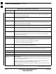
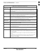
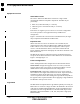
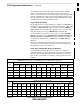
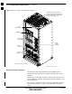
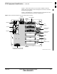
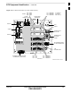
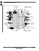
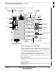
Table Of Contents
- Chapter 1: Introduction
- Chapter 2: Preparatory Tasks
- Chapter 3: Optimization/Calibration
- Introduction to Optimization and Calibration
- Preparing the LMF
- Overview of Packet BTS Files
- LMF Features and Installation Requirements
- LMF File Structure Overview
- LMF Home Directory
- NECF Filename Conventions and Directory Location
- LMF Installation and Update Procedures
- Copy BTS and CBSC CDF (or NECF) Files to the LMF Computer
- Creating a Named HyperTerminal Connection for MMI Communication
- Span Lines - Interface and Isolation
- LMF to BTS Connection
- Switching the Active LAN - LMF I/O Panel 10Base-2 LAN Connection

BTS Equipment Identification – continued
1-18 1X SC 4812T Lite BTS Optimization/ATP FEB 2005
PRELIMINARY
For clarity, doors are not shown.
Power
Supply
Modules
SCCP
Shelves
Fan Module
ti-CDMA-WP-00213-v01-ildoc-ftw
Power
Breaker
Panel
Amplifiers
I/O Interconnect Panel (Shown is a
2-Carrier Stand Alone Configuration; all
I/O Panel Configurations are detailed in
Figure 1-3 through Figure 1-7)
Filter
Compartment
Figure 1-2: 1X SCt4812T–Lite BTS Frame (Typical)
Internal Assemblies and FRUs
The BTS Frame houses the Fan Modules, Small CDMA Channel
Processor (SCCP) Cage, RF Power Amplifier Modules, PA Trunking
Modules.
RF Filtering includes: DRF – Duplexers with TX Filter, RX Filter, and
Diversity RX Filter and TRF – Non-Duplexed TX Filter, RX Filter, and
Diversity RX Filter.
Power System components include an AC Power Input/Filter, DC Filter,
Power Alarm Card (PAC), +27V DC Power Distribution Assembly
(PDA).
1