
User's Manual

Initial Power Up – continued
PRELIMINARY
1X SCt4812ET Lite BTS Optimization/ATP
08/01/2001
2-16
Table 2-7: Battery Charge Test (Connected Batteries)
Step Action
3 The current in each string should be approximately equal (within + 5 amps).
4 Allow a few minutes to ensure that the battery charge current stabilizes before taking any further
action. Recheck the battery current in each string. If the batteries had a reasonable charge, the current
in each string should reduce to less than 5 amps.
5
Recheck the DC output voltage. It should remain the same as measured in step 4 of the frame DC
Power Application and Test (Table 2-6).
NOTE
If discharged batteries are installed, the MAP AMP display may indicate approximately 288 amps for
a two–carrier frame (four rectifiers) or 216 amps for a single–carrier frame (three rectifiers).
Alternately, all bar graph elements may be lighted on the rectifiers during the charge test. Either
indication shows that the rectifiers are at full capacity and are rapidly charging the batteries. It is
recommended in this case that the batteries are allowed to charge and stabilize as in the above step
before commissioning the site. This could take several hours.
Battery Discharge Test
Perform the test procedure in Table 2-8 only when the battery current is
less than 5 Amps per string. Refer to Table 2-7 on the procedures for
checking current levels.
Table 2-8: Battery Discharge Test
Step Action
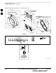
1 Turn the BATT TEST switch on the MAP ON (Figure 2-9). The rectifier output voltage and current
should decrease by approximately 10% as the batteries assume the load. Alarms for the MAP may
occur.
2 Measure the individual battery string current using the clamp–on DC current probe and DMM. The
battery discharge current in each string should be approximately the same (within +
5 amps).
3 Turn BATT TEST switch OFF.
Failure to turn off the MAP BATT TEST switch before
leaving the site will result in low battery capacity and
reduce battery life.
CAUTION
2