
User's Manual

Initial Power Up – continued
08/01/2001
2-9
1X SCt4812ET Lite BTS Optimization/ATP
PRELIMINARY
Table 2-3: DC Power System Pre–Power Application Test
Step Action
14 Carefully reconnect each LPA cable one at a time. Repeat step 10 after reconnecting each cable.
S A typical response is that the ohmmeter will steadily climb in resistance as module input capacitors
charge, finally indicating between 300 Ω minimum and 900 Ω. maximum.
15 Set the Pilot Beacon, both Heat Exchanger, ETIB, and Options circuit breakers to ON one at a time.
Repeat step 10 after pushing in each circuit breaker.
16 Set all DC PDA circuit breakers to OFF (pulled out).
Failure to properly connect the external AC power cable
will damage the surge protection module inside the ACLC.
CAUTION
External AC Power Connection
Verification
Following verification of frame DC power system integrity, external AC
power connections must be verified. To accomplish this, the series of AC
voltage measurements specified in Table 2-4 is required.
Table 2-4: AC Voltage Measurements
Step Action
1
NOTE
This procedure is required only after external AC power wiring has been initially connected or
removed and reconnected to the frame.
n WARNING
Ensure the frame is unpowered by setting the facility circuit breaker controlling external AC power
supplied to the frame to OFF.
Physically verify all DC PDA circuit breakers are set to OFF (pulled out), and all battery shelf circuit
breakers are OFF (pulled out).
2 Open the ACLC circuit breaker access door, and set all ACLC circuit breakers to OFF (down).
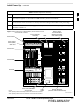
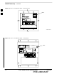
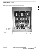
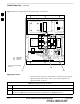
3 Remove the four screws securing the ACLC front panel assembly, and remove the ACLC front panel
assembly to gain access to the AC circuit breaker input terminals (Figure 2-8).
4 Apply external AC power to the frame by setting the facility circuit breaker to ON.
. . . continued on next page
2