
User's Manual

Internal Assembly Location and Identification – continued
08/01/2001
1-21
1X SCt4812ET Lite BTS Optimization/ATP
PRELIMINARY
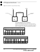
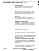
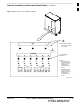
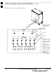
Rectifiers
The rectifiers (Figure 1-3) convert AC power supplied to the frame to
+27.4 Vdc which powers the frame and maintains the charge of the
back–up batteries. Rectifier positions are numbered 1 through 4 from left
to right when facing the frame. Single–carrier frames are equipped with
three rectifiers installed in positions 1, 2, and 3. Two–carrier frames are
equipped with four rectifiers. The number of rectifiers supplied with
each configuration provides N+1 redundancy.
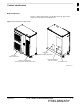
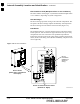
RF Diagnostic Subsystem (RFDS)
The RFDS (Figure 1-5) provides the capability for remotely monitoring
the status of the SC4812ET Lite transmit and receive paths. For
IS–95A/B operation, the RFDS is a COBRA model. To support 1X
operation, the RFDS must the 1X–capable COBRA–II.
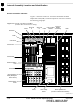
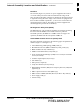
Small CDMA Channel Processor (SCCP) Shelf
The SCCP shelf has provisions for the following types and quantities of
modules (Figure 1-3 and Figure 1-5):
S Alarm Monitoring and Reporting (AMR) cards (2)
S Broadband Transceiver (BBX2 or BBX–1X) cards, primary (6)
S BBX2 or BBX–1X card, redundant (1)
S CDMA Clock Distribution (CCD) cards (2)
S Clock Synchronization Manager (CSM) on two cards (one with GPS
receiver, if ordered)
S Combiner Input/Output (CIO) card (1)
S Fan modules (2)
S Filler panel (as required)
S Group Line Interface (GLI2) cards (2)
S High Stability Oscillator (HSO)/Low Frequency Receiver (LFR) card
(Optional) (1)
S Multi–coupler Preselector Cards (MPC3) (2)
S Multi–Channel CDMA (MCC8E, MCC24, or MCC–1X) cards (4)
S Power supply cards (2)
S Switch card (1)
1