
User's Manual

Power Delta Calibration – continued
08/01/2001
H-9
1X SCt4812ET Lite BTS Optimization/ATP
PRELIMINARY
Agilent 8935 series E6380A
Power Delta Calibration
The Agilent E6380A (formerly HP8935) communications test set
modified with either option 200 or R2K and E4432B signal generator
test equipment combination can be used for ISC of IS–2000 CDMA 1X
as well as IS–95A/B operation modes. The power delta calibration is
performed on the E6380A. After the offset value has been calculated,
add it to the TX cable loss value.
Follow the procedure in Table H-3 to perform the Agilent E6380A
Power Delta Calibration procedure.
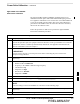
Table H-3: Agilent E6380A Power Delta Calibration Procedure
Step Action
* IMPORTANT
Perform this procedure after test equipment has been allowed to warm–up and stabilize for a minimum
of 60 minutes. After it is warmed up and stabilized, calibrate the test equipment as described in the
“Test Set Calibration” section of Chapter 3.
1
Zero the Power Meter prior to connecting the power sensor to the RF cable from the signal generator.
* IMPORTANT
For best accuracy, always re–zero the power meter before connecting the power sensor to the
component being calibrated.
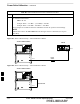
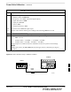
2 Connect a short RF cable between the E6380A Duplex Out port and the HP437 power sensor (see
Figure H-5).
3 Set the E6380A signal source as follows:
– Measure mode to CDMA Gen
– Frequency to the CDMA Calibration target frequency
– CW RF Path to IQ
– Output Port to Dupl
– Data Source to Random
– Amplitude to 0 dBm
4 Measure and record the power value reading on the HP437 Power Meter.
5 Record the Power Meter reading as result A ________________________.
6 Turn off the E6380A signal source output, and disconnect the HP437.
NOTE
Leave the settings on the source E6380A for convenience in the following steps.
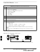
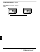
7 Connect the short RF cable between the E6380A Duplex Out port and the RF–IN/OUT port (see
Figure H-6).
8 Ensure that the source E6380A settings are the same as in Step 3.
. . . continued on next page
H