
User's Manual

Module Front Panel LED Indicators and Connectors – continued
PRELIMINARY
1X SCt4812ET Lite BTS Optimization/ATP
08/01/2001
6-32
GLI2 Pushbuttons and
Connectors
RESET Pushbutton – Depressing the RESET pushbutton causes a
partial reset of the CPU and a reset of all board devices. GLI2 will be
placed in the OOS_ROM state
MMI Connector – The RS–232MMI port connector is intended to be
used primarily in the development or factory environment but may be
used in the field for debug/maintenance purposes.
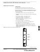
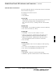
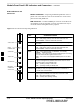
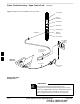
MMI PORT
CONNECTOR
ACTIVE LED
STATUS RESET ALARM SPANS MASTER MMI ACTIVE
STATUS LED
RESET
PUSHBUTTON
ALARM LED
SPANS LED
MASTER LED
Figure 6-3: GLI2 Front Panel Operating Indicators
STATUS OFF - operating normally
ON - briefly during powerĆup when the Alarm LED turns OFF.
SLOW GREEN - when the GLI2 is INS (inĆservice)
RESET
ALARM OFF - operating normally
ON - briefly during powerĆup when the Alarm LED turns OFF.
SLOW GREEN - when the GLI2 is INS (inĆservice)
SPANS
MASTER
MMI PORT
CONNECTOR
ACTIVE
LED OPERATING STATUS
All functions on the GLI2 are reset when pressing and releasing
the switch.
ON - operating normally in active card
OFF - operating normally in standby card
Shows the operating status of the redundant cards. The redundant
card toggles automatically if the active card is removed or fails
ON - active card operating normally
OFF - standby card operating normally
The pair of GLI2 cards include a redundant status. The card in the
top shelf is designated by hardware as the active card; the card in
the bottom shelf is in the standby mode.
OFF - card is powered down, in initialization, or in standby
GREEN - operating normally
YELLOW - one or more of the equipped initialized spans is receiving
a remote alarm indication signal from the far end
RED - one or more of the equipped initialized spans is in an alarm
state
An RSĆ232, serial, asynchronous communications link for use as
an MMI port. This port supports 300 baud, up to a maximum of
115,200 baud communications.
FW00225
6