
User's Manual

Alarms Testing – continued
08/01/2001
3-93
1X SCt4812ET Lite BTS Optimization/ATP
PRELIMINARY
Rectifier Over Temperature
Alarm
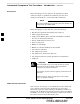
Table 3-57 gives instructions on testing the rectifier over–temperature
alarm system.
Table 3-57: Rectifier Over–Temperature Alarm
Step Action
1
Remove the 14 tamper–resistant Torx fasteners securing the rear access panel to the rear of the frame
(Figure 2-1), and remove the rear access panel.
NOTE
Panel fastener type can be either T–27 button head or T–30 pan head.
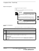
2 Looking up through the frame rear access opening, locate the rear of the MAP.
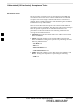
3 Remove the jumper plug from connector J8 on the rear panel of the MAP (Figure 3-22). The
following conditions should occur:
S Contacts on K1 and K2 change states (K1 now closed and K2 open).
S The CDMA LMF reports an alarm condition as BTS Relay #26 contacts.
4 Reinstall the jumper plug in connector J8, and verify that all alarm conditions have cleared.
5 Reinstall the frame rear access panel, securing it with the 14 tamper–resistant Torx fasteners removed
in step 1.
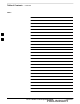
Figure 3-22: MAP Connector J8 (Rear of MAP)
SC4812ETL0021–1
J4
J5 J1
J12
J3 J8 J9 J7
J2
CONNECTOR J8
Before Leaving the site
If no further operations are required after performing the alarm tests,
complete the requirements in Table 5-8 before leaving the site.
3