
User's Manual

Bay Level Offset Calibration – continued
PRELIMINARY
1X SCt4812ET Lite BTS Optimization/ATP
08/01/2001
3-68
(2500 corresponds to –125 dBm and 27500 corresponds to +125
dBm).
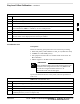
S The 10 calibration points for each slot/branch combination must be
stored in order of increasing frequency. If less than 10 points
(frequencies) are calibrated, the BLO data for the highest frequency
calibrated is written into the remainder of the 10 points for that
slot/branch.
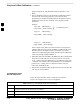
Example:
C[1]=384
(odd cal entry)
C[2]=19102 (even cal entry)
C[3]=777 (odd cal entry)
C[4]=19086 (even cal entry)
C[19]=777 (odd cal entry)
C[20]=19086 (even cal entry)
.
.
.
= 1 “calibration point”
In the example above, BLO was measured at only two frequencies
(channels 384 and 777) for SCCP slot BBX–1 transmit (Table 3-32).
The BLO data for the highest frequency measured (777) will be
written to the remaining eight transmit calibration points (defined by
entries C[5] through C[20]) for BBX2–1.
S When BLO data is downloaded to the BBXs, the data is downloaded
to the devices in the order it is stored in the CAL file. TxCal data
(C[1] – C[60]) is sent first. BBX2 slot 1’s 10 calibration points (C[1]
– C[20]) are sent initially, followed by BBX2 slot 2’s 10 calibration
points (C[21] – C[40]), and so on. The RxCal data is sent next,
followed by the RxDCal data.
S Temperature compensation data (TempLevelCal) is also stored in the
CAL file for each slot Block.
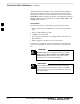
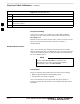
Test Equipment Setup:
RF Path Calibration
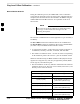
Follow the steps outlined in Table 3-33 and refer as needed to
Figure 3-15 or Figure 3-16 to set up test equipment.
Table 3-33: Set Up Test Equipment (RF Path Calibration)
Step Action
1 If it has not already been done, refer to the procedure in Table 3-6 to interface the CDMA LMF
computer terminal to the frame LAN A connector.
2 If it has not already been done, refer to Table 3-7 to start a GUI LMF session.
3 If required, calibrate the test equipment per the procedure in Table 3-25.
3