
User's Manual

CSM System Time – GPS & LFR/HSO Verification – continued
08/01/2001
3-39
1X SCt4812ET Lite BTS Optimization/ATP
PRELIMINARY
CSM Frequency Verification
The objective of this procedure is the initial verification of the Clock
Synchronization Module (CSM) cards before performing the RF path
verification tests.
Test Equipment Setup
(GPS & LFR/HSO Verification)
Follow the steps outlined in Table 3-19 to set up test equipment.
Table 3-19: Test Equipment Setup (GPS & LFR/HSO Verification)
Step Action
1a For local GPS (RF–GPS): Verify a CSM card with a GPS receiver is installed in the primary CSM
slot, CSM–1, and that CSM–1 is INS.
NOTE
This is verified by checking the card ejectors for kit number SGLN1145 on the card in slot 1.
1b For Remote GPS (RGPS): Verify a CSM2 card is installed in primary slot CSM–1 and that CSM–1 is
INS.
NOTE
This is verified by checking the card ejectors for kit number SGLN4132CC or subsequent.
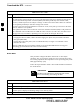
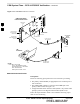
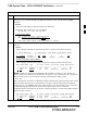
2 Remove CSM–2 (if installed) and connect a serial cable from the LMF COM 1 port (via null modem
card) to the MMI port on CSM–1 (see Figure 3-13).
3 Reinstall CSM–2.
4 Start an MMI communication session with CSM–1 by using the Windows desktop shortcut icon (see
Table 3-11) .
5 When the terminal screen appears press the Enter key until the CSM> prompt appears.
In the power entry compartment, connect the GPS antenna
to the RF GPS connector ONLY. Damage to the GPS
antenna and/or receiver can result if the GPS antenna is
inadvertently connected to any other RF connector.
CAUTION
3