
User's Manual

Download the BTS – continued
08/01/2001
3-35
1X SCt4812ET Lite BTS Optimization/ATP
PRELIMINARY
Table 3-16: Select CSM Clock Source
Step Action
6 Click on the OK button. A status report window is displayed showing the results of the selection
action.
7 Click on the OK button to close the status report window.
Enable CSMs
Each BTS CSM system features two CSM boards per site. In a typical
operation, the primary CSM locks its Digital Phase Locked Loop
(DPLL) circuits to GPS signals. These signals are generated by either an
on–board GPS module (RF–GPS) or a remote GPS receiver (R–GPS).
The GPS receiver interfaced to CSM 1 is used as the primary timing
reference and synchronizes the entire cellular system. CSM 2 provides
clock syncronization back–up, but does not have a GPS receiver.
The BTS may be equipped with a LORAN–C Low Frequency Receiver
(LFR), a High Stability Oscillator (HSO), or external 10 MHz Rubidium
source which the CSM can use as a secondary timing reference. In all
cases, the CSM monitors and determines what reference to use at a given
time.
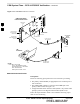
For RF–GPS, verify the CSM configured with the GPS
receiver “daughter board” is installed in the frame’s CSM 1
slot before continuing.
IMPORTANT
*
Follow the steps outlined in Table 3-17 to enable the CSMs installed in
the SCCP shelves.
Table 3-17: Enable CSMs
Step Action
1
NOTE
If equipped with two CSMs, enable CSM–2 first.
Click on the target CSM.
From the Device pull down, select Enable.
2 A status report is displayed confirming change in the device(s) status.
Click OK to close the status report window.
NOTE
S CSM 1 houses the GPS receiver. The enable sequence can take up to one hour (see below).
S FAIL may be shown in the status report table for enable action. If Waiting For Phase Lock is shown
in the Description field, the CSM changes to the Enabled state after phase lock is achieved.
. . . continued on next page
3