
User's Manual

Initial Power–Up Test – continued
5-12 1X SC480 BTS Hardware Installation, Optimization/ATP, and FRU Jun 2004
DRAFT
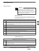
Table 5-11: Procedure cCLPA Initial Power–Up
Step Action
2 If not already done, remove cCLPA I/O panel cover.
3 Connect DC power to cCLPA I/O board DC terminal block.
4 Turn on DC power source.
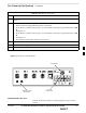
5 Using a DMM (set to VDC), measure the voltage at the cCLPA I/O board terminal block.
DC voltage should measure in the range of +20 to +34 VDC. Adjust DC power source as necessary.
6 Remove DMM and install I/O panel cover.
7 On the cCLPA, push in 20 A circuit breaker.
Outdoor Configuration Initial
Power Test
TME Initial Power–Up
Perform the procedure Table 5-12 in before applying any power to the
BTS and HMS.
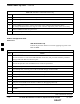
Table 5-12: TME DC Initial Power–Up Test
Step Action
* IMPORTANT
To avoid extensive re–work of the TME and BTS connections, this procedure should be performed
after the TME with BTS is mounted in place.
NOTE
Perform this procedure after the PDE has been verified as operational.
1 Verify that DC power from the PDE is OFF.
2 If not already done, route DC power cable from PDE through conduit to TME.
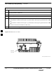
3 If not already done, remove protective cover from voltage connection on PDA.
4 Use a Phillips screw driver to remove screws from DC power connector on PDA.
5 Set lug of “–” wire in the RTN location and secure with screw.
6 Set lug of “+” wire in the +27 VDC location and secure with screw.
7 Verify that 1U and TME circuit breakers on PDA are disengaged (pulled out).
8 Turn on PDE supplying the TME.
9 Using a DMM set to VDC, measure the voltage at the PDA connector. DMM should indicate +20 to
+34 VDC.
10 If not already done, connect PDA to HMS Controller (D–connector)
table continued on next page
5