
User's Manual
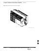

TME Power Distribution Assembly – continued
9-72 1X SC480 BTS Hardware Installation, Optimization/ATP, and FRU Jun 2004
DRAFT
Table 9-41: Procedure to Remove PDA
Step Action
8 Gently pull out PDA far enough to disconnect cables at the rear.
9 Remove PDA.
Install PDA
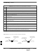
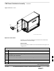
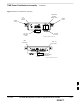
Follow the procedure in Table 9-42 to install the PDA. See Figure 9-26
or Figure 9-27.
Table 9-42: Procedure to Install PDA
Step Action
1 Hold PDA near its slot in the TME and connect the cables (previously disconnected) to the rear of the
PDA.
2 Slide PDA in and secure to TME chassis by tightening the captive screws.
3 Place ground lug on ground studs of the PDA and secure using two M6 nuts and washers. Torque nuts
to 3.4 N–M (30 in–lbs).
4 Verify that circuit breakers are disengaged (pulled out or set to “O” position).
5 Verify that DC power source is OFF.
6 Connect +27 V power plug.
7 Turn on DC power.
8 On PDA, set circuit breaker switch to “1” position.
9 Push in 1U circuit breaker.
10 Notify operator that replacement is complete and verify that no new alarms have been generated and
that old alarms are cleared.
9