
User's Manual
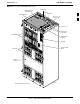
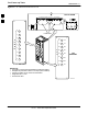
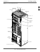
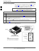
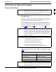
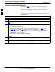
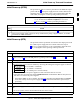
Table Of Contents
- Contents
- Chapter 1 Introduction
- Chapter 2 Preliminary Operations
- Chapter 3 Optimization/Calibration

Initial Power–up Tests and Procedures
68P09258A31–A
Oct 2003
1X SCt 4812T BTS Optimization/ATP
2-16
Table 2-7: Initial Power–up (BTS)
Step Action
7 Set the LPA breakers to the ON position (per configuration) by pushing them IN one at a time. See
Figure 1-13 on page 1-32 or Figure 1-14 on page 1-33 for configurations and Figure 2-3 on page 2-8
or Figure 2-5 on page 2-10 for LPA breaker panel layout.
On +27 V frames, engage (push) LPA circuit breakers.
S Confirm LEDs on LPAs light.
On –48 V frames, engage (push) LPA PS circuit breakers.
S Confirm LPA PS fans start.
S Confirm LEDs on –48 V power converter boards light.
S Confirm LPA fans start.
S Confirm LEDs on LPAs light.
8 After all cards/modules have been seated and verified, use a digital voltmeter to verify power supply
output voltages at the top of the frame remain within specifications: +27.0 Vdc or –48 Vdc
nominal.
9 Repeat Steps 1 through 8 for additional co–located frames (if equipped).
2