
User's Manual
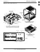
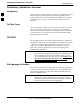
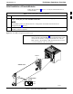
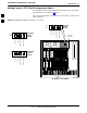
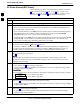
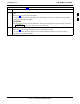
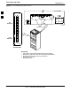
Table Of Contents
- Contents
- Chapter 1 Introduction
- Chapter 2 Preliminary Operations
- Chapter 3 Optimization/Calibration

Pre–Power–up Tests
68P09258A31–A
Oct 2003
1X SCt 4812T BTS Optimization/ATP
2-6
DC Power Pre-test (BTS Frame)
Before applying any power to the BTS frame, follow the procedure in
Table 2-2 while referring to Figure 2-3 and Figure 2-4 for +27 V
systems or to Figure 2-5 and Figure 2-6 for –48 V systems to verify
there are no shorts in the BTS frame DC distribution system.
Table 2-2: DC Power Pre–test (BTS Frame)
Step Action
1 Physically verify that all DC power sources supplying power to the frame are OFF or disabled.
2 On each frame:
S Unseat all circuit boards (except CCD and CIO cards) in the C–CCP shelf and LPA shelves, but
leave them in their associated slots.
S Set C–CCP shelf breakers to the OFF position by pulling out power distribution breakers (labeled
C–CCP 1, 2, 3 on the +27 V BTS C–CCP power distribution panel and labeled POWER
1,4,5,2,6,7,3,8,9 on the –48 V C–CCP power distribution panel).
S Set LPA breakers to the OFF position by pulling out the LPA breakers (8 breakers, labeled 1A–1B
through 4C–4D – located on the C–CCP power distribution panel in the +27 V BTS or on the
power conversion shelf power distribution panel in the –48 V BTS).
3 Verify that the resistance from the power (+ or –) feed terminals with respect to the ground terminal on
the top of the frame measures >
500 Ω (see Figure 2-3).
S If reading is < 500 Ω, a short may exist somewhere in the DC distribution path supplied by the
breaker. Isolate the problem before proceeding. A reading > 3 M
Ω could indicate an open (or
missing) bleeder resistor (installed across the filter capacitors behind the breaker panel).
4 Set the C–CCP (POWER) breakers to the ON position by pushing them IN one at a time. Repeat
Step 3 after turning on each breaker.
NOTE
NOTE
If the ohmmeter stays at 0 Ω after inserting any board/module, a short probably exists in that
board/module. Replace the suspect board/module and repeat the test. If test still fails, isolate the
problem before proceeding.
5 Insert and lock the DC/DC converter modules for the C–CCP shelf and into their associated slots one
at a time. Repeat Step 3 after inserting each module.
S A typical response is that the ohmmeter steadily climbs in resistance as capacitors charge, finally
indicating approximately 500
Ω.
! CAUTION
! CAUTION
Verify the correct power/converter modules by observing the locking/retracting tabs appear as follows:
–
(in +27 V BTS C–CCP shelf)
–
(in –48 V BTS C–CCP shelf)
STPN4045A
PWR CONV CDMA RCVR
STPN4009
PWR CONV CDMA RCVR
6 Insert and lock all remaining circuit boards and modules into their associated slots in the C–CCP shelf.
Repeat Step 3 after inserting and locking each board or module.
S A typical response is that the ohmmeter steadily climbs in resistance as capacitors charge, stopping
at approximately 500
Ω..
7 Set the LPA breakers ON by pushing them IN one at a time.
Repeat Step 3 after turning on each breaker.
S A typical response is that the ohmmeter will steadily climb in resistance as capacitors charge,
stopping at approximately 500
Ω..
. . . continued on next page
2