
User's Manual
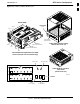
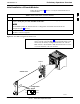
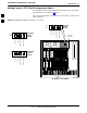
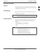
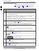
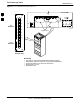
Table Of Contents
- Contents
- Chapter 1 Introduction
- Chapter 2 Preliminary Operations
- Chapter 3 Optimization/Calibration

BTS Sector Configuration68P09258A31–A
Oct 2003
1X SCt 4812T BTS Optimization/ATP
1-35
Figure 1-16: CDMA (COBRA) RFDS Layout
AMR–B
(RS–485 SERIAL)
AMR–A
(RS–485 SERIAL)
Cobra RFDS external housing
(Shown With Cover off)
POWER SUPPLY
ON/OFF ROCKER
SWITCH
MMI PORT AND
PWR/ALARM LED
Cobra RFDS Field Replaceable Unit (FRU)
(shown removed from external housing)
CHASSIS GND
POWER
CONNECTOR
Cobra RFDS RF connector
panel detail
(shown from rear)
ELECTRICAL GND
FRONT VIEW
CASU 1
CASU 2
FWTIC
SUA
ESN LABEL
(FOR SC XXXX SERIES BTS)
MMI
LEDS
ESN LABEL
(FOR SC 6XX SERIES BTS)
FW00138
1