
User's Manual
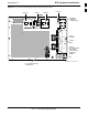
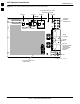
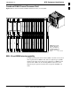
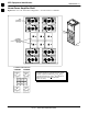
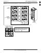
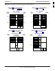
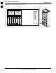
Table Of Contents
- Contents
- Chapter 1 Introduction
- Chapter 2 Preliminary Operations
- Chapter 3 Optimization/Calibration

BTS Equipment Identification68P09258A31–A
Oct 2003
1X SCt 4812T BTS Optimization/ATP
1-29
Figure 1-12: –48 V SC 4812T PA Configuration – 4 Carrier, 3–Sector with 2:1 Combiners
PA1A
PA1B
Note
No adjacent carriers may exist within the same TX filter
combiner. “Adjacent” is defined as f
c1
and f
c2
being
1.25 MHz apart (center–to–center). “Non–adjacent” is
defined as f
c1
and f
c2
being >2.50 MHz apart
(center–to–center).
4–CARRIER CONFIGURATION
CARRIER CARRIER
PA1C
PA1D
PA3C
PA3D
PA2A
PA2B
PA2C
PA2D
PA4C
PA4D
FW00481
1
2
3
4
5
6
1
2
3 4
1
2
3
4
5
6
PA3A
PA3B
PA4A
PA4B
FAN
MODULE
(TYPICAL)
FILTERS /
COMBINERS
(2 TO 1 COMBINER
SHOWN)
–48 Volt
SC 4812T
1