
User's Manual

LMF to BTS Connection68P09258A31–A
Oct 2003
1X SCt 4812T BTS Optimization/ATP
3-17
LMF to BTS Connection
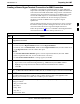
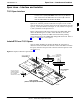
Connect the LMF to the BTS
The LMF is connected to the LAN A or B connector located on the left
side of the frame’s lower air intake grill, behind the LAN Cable Access
door (see Figure 3-3).
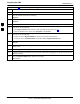
Table 3-5: LMF to BTS Connection
Step Action
1 To gain access to the connectors, open the LAN cable access door, then pull apart the fabric covering
the BNC “T” connector (see Figure 3-3).
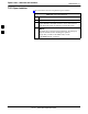
2 Connect the LMF to the LAN A BNC connector via PCMCIA Ethernet Adapter with an unshielded
twisted–pair (UTP) Adapter and 10BaseT/10Base2 converter (powered by an external AC/DC
transformer). If there is no login response, connect the LMF to the LAN B connector. If there is still
no login response, see Table 6-1, Login Failure Troubleshooting Procedures.
NOTE
Xircom Model PE3–10B2 or equivalent can also be used to interface the LMF Ethernet connection to
the frame connected to the PC parallel port, powered by an external AC/DC transformer. In this case,
the BNC cable must not exceed 91 cm (3 ft) in length.
* IMPORTANT
The LAN shield is isolated from chassis ground. The LAN shield (exposed portion of BNC connector)
must not touch the chassis during optimization.
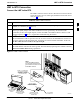
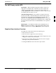
Figure 3-3: LMF Connection Detail
NOTE:
Open LAN CABLE ACCESS
door. Pull apart Velcro tape and
gain access to the LAN A or LAN
B LMF BNC connector.
LMF BNC “T” CONNECTIONS
ON LEFT SIDE OF FRAME
(ETHERNET “A” SHOWN;
ETHERNET “B” COVERED
WITH VELCRO TAPE)
Á
Á
Á
LMF COMPUTER
TERMINAL WITH
MOUSE
PCMCIA ETHERNET
ADPATER & ETHERNET
UTP ADAPTER
10BASET/10BASE2
CONVERTER CONNECTS
DIRECTLY TO BNC T
115 VAC POWER
CONNECTION
Á
FW00140
Á
UNIVERSAL TWISTED
PAIR (UTP) CABLE (RJ11
CONNECTORS)
3