
User's Manual

Test Set Calibration
68P09258A31–A
Oct 2003
1X SCt 4812T BTS Optimization/ATP
3-82
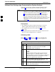
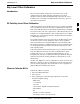
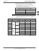
Table 3-30: Calibrating Non–Duplexed RX Cables Using a Signal Generator &Spectrum Analyzer
Step Action
NOTE
When preparing to calibrate a BTS with Duplexed TX and RX the RX cable calibration must be done
using calibration setup in Figure 3-25 and the procedure in Table 3-29.
1 Connect a short test cable between the spectrum analyzer and the signal generator as shown in
Figure 3-26, detail “A” (top portion of figure).
2 Set signal generator to –10 dBm at the customer’s RX frequency of:
824–849 for North American Cellular or 1850–1910 MHz band for North American PCS
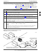
3 Use spectrum analyzer to measure signal generator output (see Figure 3-26, A) and record the value.
4 Connect the test setup, as shown in the lower portion of the diagram (see Figure 3-26, B) to measure
the output at the customer’s RX frequency of:
824–849 for North American Cellular or 1850–1910 MHz band for North American PCS
Record the value at point B.
5
Calibration factor = (value measured with detail “A” setup) – (value measured with detail “B” setup)
Example: Cal factor = –1 dBm – (–53.5 dBm) = 52.5 dB
NOTE
The short cable is used for calibration only. It is not part of the final test setup. After calibration is
completed, do not re-arrange any cables. Use the test cable configuration as is to ensure test
procedures use the correct calibration factor.
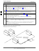
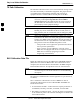
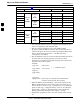
Figure 3-26: Cal Setup for Non–Duplexed RX Test Cabling
Using Signal Generator & Spectrum Analyzer
Spectrum
Analyzer
Signal
Generator
A
B
Spectrum
Analyzer
SHORT
TEST
CABLE
SHORT TEST
CABLE
CONNECTION TO THE HP PCS
INTERFACE OUTPUT PORT
DURING RX MEASUREMENTS.
Signal
Generator
BULLET
CONNECTOR
LONG
CABLE 2
CONNECTION TO THE RX PORTS
DURING RX MEASUREMENTS.
3