
User's Manual

Test Set Calibration68P09258A31–A
Oct 2003
1X SCt 4812T BTS Optimization/ATP
3-81
Calibrate Test Cabling Using Signal Generator & Spectrum Analyzer
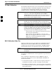
Follow the procedure in Table 3-29 to calibrate the TX/Duplexed RX
cables using a signal generator and spectrum analyzer. Refer to
Figure 3-25, if required. Follow the procedure in Table 3-30 to calibrate
the Non–Duplexed RX cables using the signal generator and spectrum
analyzer. Refer to Figure 3-26, if required.
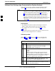
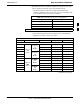
Table 3-29: Calibrating TX/Duplexed RX Cables Using Signal Generator & Spectrum Analyzer
Step Action
1 Connect a short test cable between the spectrum analyzer and the signal generator as shown in
Figure 3-25, detail “A” (top portion of figure).
2 Set signal generator to 0 dBm at the customer frequency of:
869–894 MHz for North American Cellular or 1930–1990 MHz for North American PCS
3 Use spectrum analyzer to measure signal generator output (see Figure 3-25, A) & record the value.
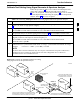
4 Connect the spectrum analyzer’s short cable to point B, (as shown in the lower right portion of the
diagram) to measure cable output at customer frequency of:
869–894 MHz for North American Cellular or 1930–1990 MHz for North American PCS
Record the value at point B.
5
Calibration factor = (value measured with detail “A” setup) – (value measured with detail “B” setup)
Example: Cal factor = –1 dBm – (–53.5 dBm) = 52.5 dB
NOTE
The short cable is used for calibration only. It is not part of the final test setup. After calibration is
completed, do not re-arrange any cables. Use the test cable configuration as is to ensure test
procedures use the correct calibration factor.
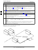
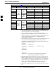
Figure 3-25: Cal Setup for TX/Duplexed RX Test Cabling
Using Signal Generator & Spectrum Analyzer
50 OHM
TERMINATION
30 DB
DIRECTIONAL
COUPLER
Spectrum
Analyzer
Signal
Generator
A
Spectrum
Analyzer
40W NON–RADIATING
RF LOAD
B
SHORT TEST CABLE
Signal
Generator
THIS WILL BE THE CONNECTION TO THE HP8481A POWER
SENSOR DURING TX BAY LEVEL OFFSET TEST AND TO THE
PCS INTERFACE BOX INPUT PORT DURING TX ATP TESTS.
SHORT
TEST
CABLE
THIS WILL BE THE CONNECTION TO
THE TX PORTS DURING TX BAY LEVEL
OFFSET TEST AND TX ATP TESTS.
CABLE FROM 20 DB @ 20W ATTENUATOR TO THE
PCS INTERFACE OR THE HP8481A POWER SENSOR.
A
ONE 20DB 20 W IN
LINE ATTENUATOR
FW00293
3