
User's Manual

Test Set Calibration
68P09258A31–A
Oct 2003
1X SCt 4812T BTS Optimization/ATP
3-80
Calibrate Test Cabling using Communications System Analyzer
Cable Calibration is used to calibrate both TX and RX test cables.
Appendix F covers the procedures for manual cable calibration.
NOTE
LMF cable calibration cannot be accomplished using an HP8921
analyzer for 1.7/1.9 GHz. A different analyzer type or the signal
generator and spectrum analyzer method (Table 3-29 and
Figure 3-25) must be used. Cable calibration values must be
manually entered into the LMF cable loss file if the signal
generator and spectrum analyzer method is used. To use the
HP8921A for manual test cable configuration calibration for 800
MHz BTSs, refer to the Manual Cable Calibration section of
Appendix F.
Prerequisites
S Test equipment is turned on and has warmed up for at least 60
minutes. Agilent E7495A requires only 30 minute warmup.
S Test equipment has been selected in the LMF (Table 3-25 or
Table 3-26).
S Test equipment has been calibrated and correctly connected for the
type of test cable configuration to be calibrated.
Calibrating cables
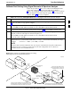
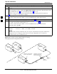
Refer to Figure 3-12, Figure 3-13, or Figure 3-14 and follow the
procedure in Table 3-28 to calibrate the test cable configurations.
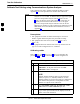
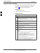
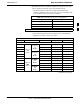
Table 3-28: Test Cabling Calibration using Comm. System Analyzer
n Step Action
1 Click Util in the BTS menu bar, and select Cable
Calibration... in the pull–down menu. A Cable
Calibration window is displayed.
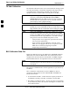
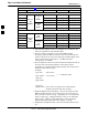
2 Enter one or more channel numbers in the Channels box
NOTE
Multiple channels numbers must be separated with a
comma, no space (i.e., 200,800). When two or more
channels numbers are entered, the cables are calibrated for
each channel. Interpolation is accomplished for other
channels as required for TX calibration.
3 Select TX and RX Cable Cal, TX Cable Cal, or RX
Cable Cal in the Cable Calibration pick list.
4 Click OK, and follow the directions displayed for each
step. A status report window will be displayed with the
results of the cable calibration.
3