
User's Manual

Test Equipment Set-up
68P09258A31–A
Oct 2003
1X SCt 4812T BTS Optimization/ATP
3-58
Test Equipment Connection Charts
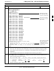
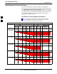
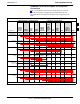
To use the following charts to identify necessary test equipment
connections, locate the communications system analyzer being used in
the
COMMUNICATIONS SYSTEM ANALYZER columns, and read down
the column. Where a dot appears in the column, connect one end of the
test cable to that connector. Follow the horizontal line to locate the end
connection(s), reading up the column to identify the appropriate
equipment and/or BTS connector.
IS–95A/B–only Test Equipment Connections
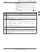
Table 3-23 depicts the interconnection requirements for currently
available test equipment supporting IS–95A/B only which meets
Motorola standards and is supported by the LMF.
Table 3-23: IS–95 A/B Test Equipment Setup
COMMUNICATIONS SYSTEM ANALYZER ADDITIONAL TEST EQUIPMENT
SIGNAL
Cyber–
Test
Advant-
est
R3465
HP
8935
HP
8921A
HP 8921
W/PCS
Power
Meter
GPIB
Inter-
face LMF
30 dB Direction-
al Coupler & 20
dB Pad*
BTS
EVEN SECOND
SYNCHRONIZATION
EVEN
SEC
REF
EVEN SEC
SYNC IN
EVEN
SECOND
SYNC IN
EVEN
SECOND
SYNC IN
EVEN
SECOND
SYNC IN
19.6608 MHZ
CLOCK
TIME
BASE IN
CDMA
TIME BASE
IN
EXT
REF IN
CDMA
TIME
BASE IN
CDMA
TIME
BASE IN
CONTROL
IEEE 488 BUS
IEEE
488
GPIB HP–IB HP–IB GPIB
SERIAL
PORT
HP–IB HP–IB
TX TEST
CABLES
RF
IN/OUT
INPUT
50–OHM
RF
IN/OUT
TX1–6
RF
IN/OUT
RF
IN/OUT
30 DB COUPLER
AND 20 DB PAD
RX TEST
CABLES
RF GEN
OUT
RF OUT
50–OHM
RX1–6
DUPLEX
OUT
RF OUT
ONLY
SYNC
MONITOR
FREQ
MONITOR
RF
IN/OUT
3