
User's Manual

Test Equipment Set-up
68P09258A31–A
Oct 2003
1X SCt 4812T BTS Optimization/ATP
3-56
Test Equipment Set-up
Connecting Test Equipment to the BTS
The following equipment is required to perform optimization:
S LMF
S Test set
S Directional coupler and attenuator
S RF cables and connectors
S Null modem cable (see Figure 3-10)
S GPIB interface box
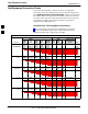
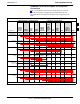
Refer to Table 3-23 and Table 3-24 for an overview of connections for
test equipment currently supported by the LMF. In addition, see the
following figures:
S Figure 3-16 and Figure 3-17 show the test set connections for TX
calibration.
S Figure 3-19 and Figure 3-20 show test set connections for IS–95 A/B
optimization/ATP tests.
S Figure 3-21 shows test set connections for IS–95 A/B and
CDMA 2000 optimization/ATP tests.
S Figure 3-23 and Figure 3-24 show typical TX and RX ATP setup with
a directional coupler (shown with and without RFDS).
Test Equipment GPIB Address Settings
All test equipment is controlled by the LMF through an IEEE–488/GPIB
bus. To communicate on the bus, each piece of test equipment must have
a GPIB address set which the LMF will recognize. The standard address
settings used by the LMF for the various types of test equipment items
are as follows:
S Signal generator address: 1
S Power meter address: 13
S Communications system analyzer: 18
Using the procedures included in the Verifying and Setting GPIB
Addresses section of Appendix F, verify and, if necessary, change the
GPIB address of each piece of employed test equipment to match the
applicable addresses above
.
3