
User's Manual

CSM System Time – GPS & LFR/HSO Verification
68P09258A31–A
Oct 2003
1X SCt 4812T BTS Optimization/ATP
3-54
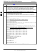
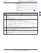
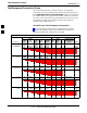
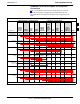
Table 3-21: LFR Initialization/Verification
Step NoteAction
4 LORAN–C LFR information (highlighted above in boldface type) is usually the #1 reference source
(verified from left to right).
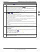
NOTE
If any of the above mentioned areas fail, verify:
– The LFR antenna is not obstructed or misaligned.
– The antenna pre–amplifier power and calibration twisted pair connections are intact and < 91.4 m
(300 ft) in length.
– A dependable connection to suitable Earth Ground is in place.
– The search list and PLL station for cellsite location are correctly configured .
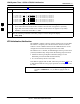
NOTE
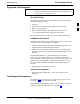
LFR functionality should be verified using the “source” command (as shown in Step 3). Use the
underlined
responses on the LFR row to validate correct LFR operation.
5 Close the Hyperterminal window.
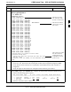
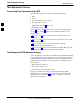
HSO Initialization/Verification
The HSO module is a full–size card that resides in the C–CCP Shelf.
This completely self contained high stability 10 MHz oscillator
interfaces with the CSM via a serial communications link. The CSM
handles the overall configuration and status monitoring functions of the
HSO. In the event of GPS failure, the HSO is capable of maintaining
synchronization initially established by the GPS reference signal for a
limited time.
The HSO is typically installed in those geographical areas not covered
by the LORAN–C system and provides the following major functions:
S Reference oscillator temperature and phase lock monitor circuitry
S Generates a highly stable 10 MHz sine wave.
S Reference divider circuitry converts 10 MHz sine wave to 10 MHz
TTL signal, which is divided to provide a 1 PPS strobe to the CSM.
3