
User's Manual

CSM System Time – GPS & LFR/HSO Verification68P09258A31–A
Oct 2003
1X SCt 4812T BTS Optimization/ATP
3-45
CSM Frequency Verification
The objective of this procedure is the initial verification of the CSM
boards before performing the RF path verification tests. Parts of this
procedure will be repeated for final verification after the overall
optimization has been completed.
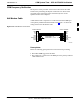
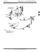
Null Modem Cable
A null modem cable is required. It is connected between the MMI port
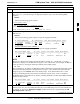
of the primary CSM and the null modem board. Figure 3-10 shows the
wiring detail for the null modem cable.
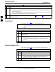
Figure 3-10: Null Modem Cable Detail
5
3
2
7
8
1
4
6
GND
RX
TX
RTS
CTS
RSD/DCD
DTR
DSR
GND
TX
RX
RTS
CTS
RSD/DCD
DTR
DSR
ON BOTH CONNECTORS
SHORT PINS 7, 8;
SHORT PINS 1, 4, & 6
9–PIN D–FEMALE 9–PIN D–FEMALE
5
2
3
7
8
1
4
6
FW00362
Prerequisites
Ensure the following prerequisites have been met before proceeding:
S The LMF is NOT logged into the BTS.
S The COM1 port is connected to the MMI port of the primary CSM via
a null modem board.
3