
User's Manual

Subscriber Unit (SU) Installation and Cabling
JAN 2002
6-15
SC300 1X BTS Hardware Installation, ATP, and FRU Procedures
DRAFT
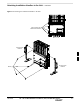
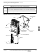
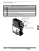
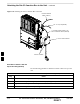
Objective
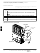
The objective of this procedure is to install the Subscriber Unit (SU) to
the unit and to install the necessary cables.
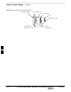
Cable Labels
The cable designations are referenced to Table 4-1 in the “Cable
Description” area of this chapter.
Required Tools and Materials
Required tools
Torque driver wrench
T30 TORX tamper bit
5/16–in. SMA 9 in–lb. break–away torque wrench
Motorola kits
The Motorola Kit described in Table 6-9 is required to do this procedure.
Table 6-9: External Subscriber Unit Kit – T529AA
Cable Qty. Part Number Description
n/a 1–4 SGLN5976A Subscriber Unit
P 1–4 3088120C03 SU RF cable
L 1–4 3087701C04 Y–Ground Cable (for external SU and Site I/O).
Motorola terminators
The following Motorola terminators in Table 6-10 are required to do this
procedure. The number of SU Terminators depends upon system
configuration.
Table 6-10: Terminations of Unused Connectors
Connector Motorola Part # Description
SU Digital 5887659C02 Terminator, Power
SC340 AC
SU Distribution 0187683C03 Terminator, SMA
(Microcell)
6