
User's Manual

Earth Ground Cabling
DRAFT
SC300 1X BTS Hardware Installation, ATP, and FRU Procedures
JAN 2002
6-10
Objective
The objective of this procedure is to attach the earth ground cabling to
one or more MicroCell units. This procedure covers just the grounding
cables that attach to the MicroCell.
Other Grounding
Considerations
Grounding considerations beyond the ground cables that attach to the
MicroCell are summarized in Appendix A. Refer to Appendix A and the
site documentation for other grounding considerations.
If your site is equipped with the optional Primary Surge Suppressor,
refer to the “Power, Earth Ground, and Battery Cabling” Procedure in
chapter 4 for information about installing the Master Ground cable.
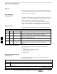
Required Cables
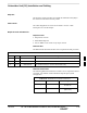
The following cables in Table 6-5 are necessary to do this procedure.
Table 6-5: Required Cables for Earth Ground Cabling
Cable Qty. Part Number Description
A 1–4 3087701C02 Ground cable, 8 -AWG, insulated copper wire. Requires one ring lug
connector. Used for Primary Surge Suppressor Installation.
B 1–4 3087701C01 Ground cable, Site I/O Junction Box to Bracket (for installations
without external Subscriber Unit).
L 1–4 3087701C04 Y–Ground Cable (for external SU and Site I/O).
Y 1 Customer
Supplied
Master Ground Cable, 6 -AWG, insulated copper wire. Used for both
Primary Surge Suppressor and non–Primary Surge Suppressor
installations.
Required Tools and Materials
The following tools are required to attach ground cabling to the
MicroCell unit.
13 mm torque wrench set to 5.0 N–M
Flathead screwdriver bit
T30 TORX bit
Procedure to Attach the Earth
Ground Cables
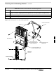
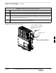
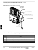
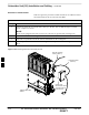
Use the following procedure to attach the ground cables. Refer to
Table 6-6 and Figure 6-7.
Table 6-6: Procedure to Attach the Earth Ground Cables
Step Action
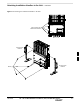
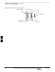
1 Remove the hex nuts and lock washers from the ground stud on the mounting bracket. Refer to
Figure 6-8.
. . . continued on next page
6